Ive never seen a DVM non clamp-on that could measure >10A of ac current, also check that the max steady state accuracy falls as a function of time (heating of wimpy shunts ). as experienced power guy, An analog panel meter movement is much more practical for attention getting E.g. safety, than small digits flipping in the background of a cheap clamp-on DMM (slow update). I've stated practical voltage isn't that far off a user calibrated dial reading so IMO a superfluous gadget add on. horses for courses and all that
Your 15A variac is rated in the range of a branch circuit breaker BUT that is a far cry from a 8A unit ~4 times the weight difference I reckon. so your practices "help" aren't applicable are they.
Your 15A variac is rated in the range of a branch circuit breaker BUT that is a far cry from a 8A unit ~4 times the weight difference I reckon. so your practices "help" aren't applicable are they.
Last edited:
Ive never seen a DVM non clamp-on that could measure >10A of ac current, also check that the max steady state accuracy falls as a function of time (heating of wimpy shunts ). as experienced power guy, An analog panel meter movement is much more practical for attention getting E.g. safety, than small digits flipping in the background of a cheap clamp-on DMM (slow update). I've stated practical voltage isn't that far off a user calibrated dial reading so IMO a superfluous gadget add on. horses for courses and all that
Your 15A variac is rated in the range of a branch circuit breaker BUT that is a far cry from a 8A unit ~4 times the weight difference I reckon. so your practices "help" aren't applicable are they.
Your claim that my advice is not generally applicable appears to be unsupported by any relevant facts except a questionable weight estimate.
For example this source
Variable Auto Transformer 120V-140V, Custom Design Variable Transformer - Ravistat, Thane, India
gives the weight of an 8 amp Variac as 6 kG and that of a 16 amp Variac as being 8.6 kG. I think the source of the numbers you presented was highly biased against larger Variacs.
For example, your posts presents no evidence that an 8 amp Variac would be permanently damaged by a current load that would trip a typical household 15 or 20 amp circuit breaker.
If I wouldn't have to run out and buy an 8 amp Variac that I obviously don't need, I'd test that for myself. IME most transformers handle x00 percent overloads for brief periods pretty well.
High current Variacs have the advantage of providing better regulation to loads operating at far lower currents.
Your apparent personal bias against digital meters and clamp on meters is exactly that, your personal bias.
A lot of DVMs provide a secondary bar graph function to address the problem of flickering numbers. I think that 2 out of my 5 have that feature.
Since clamp on meters are widely available and inexpensive, building a current loop for using one, into a bench Variac setup might be reasonable.
When I have to measure large currents with a DVM I generally either use a low valued shunt resistor or an appropriate current transformer.
I'm pretty adverse to measuring current by running it through a DVM. Just personal bias in the final analysis, but I have had some bad experiences doing it.
If one were to build an ammeter into a Variac, one could well end up using similar techniques - a current shunt or current transformer.
I developed strong preferences for certain features during several years in a high-end stereo service shop. First and foremost is a big and fast responding low-range analog ammeter, e.g. 1A range. This meter has to be protected against overload somehow, preferably by auto-switching to a higher range, but manual switching is okay. A voltmeter is necessary as well, but it has to be accurate only at 120VAC because that's where amplifier output power specs are measured.
I'll explain about the ammeter: After using it for a while, you acquire a sixth sense about failure type in the equipment under test. Shorted rectifier diodes behave very differently than shorted output transistors, for instance. If output transistors are shorted, then you need to know which channel is bad. In this case, just crank up the voltage enough to get significant but safe line current, then feel the emitter resistors. Bingo -- the site of failure is isolated in less than a minute.
I'll explain about the ammeter: After using it for a while, you acquire a sixth sense about failure type in the equipment under test. Shorted rectifier diodes behave very differently than shorted output transistors, for instance. If output transistors are shorted, then you need to know which channel is bad. In this case, just crank up the voltage enough to get significant but safe line current, then feel the emitter resistors. Bingo -- the site of failure is isolated in less than a minute.
Arny, your situation works for you, and that is great. Not all shops are the same. You may have five meters rolling around, and that is terrific. I could probably spread five meters around my bench too, but prefer the neatness of one meter for my general work and panel meters on the variac for common current and voltage readings. A lot of guys don't have five meters.
If your variac is high current, good for you, but should a young guy setting up his shop toss out his 8A variac and buy a 15A one just so he can eliminate a panel fuse or breaker and rely on the one in the basement?
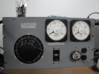
The unit Apex shows above looks like an ideal piece of bench gear. If you find it excessive, that's fine, but really, I think a lot of people would be happy as clams to have one of those.
I am sure you disagree, but that is OK too.
If your variac is high current, good for you, but should a young guy setting up his shop toss out his 8A variac and buy a 15A one just so he can eliminate a panel fuse or breaker and rely on the one in the basement?
The unit Apex shows above looks like an ideal piece of bench gear. If you find it excessive, that's fine, but really, I think a lot of people would be happy as clams to have one of those.
I am sure you disagree, but that is OK too.
big and fast responding low-range analog ammeter, e.g. 1A range.
yup another voice of practical experience . log ranges help on current and anti-log on voltage, see Apex Jr above
Last edited:
I would strongly support adding a GFCI. Any kind of failed insulation (not unknown on older tube gear) could give you a very unpleasant jolt, or worse. They are also good-essential on isolation transformers where grounding is meaningless.
A Kill-a-watt meter is a great and inexpensive way to monitor the load.
The current to pop a 15A breaker or fuse is a lot more than you might think. This is good reading for anyone dealing with power and protection: http://static.schneider-electric.us...100-400 A Frame FA-LA/FA-FC-FH/0600DB0105.pdf Essentially 45A will take 10 seconds to trip a generic 15A breaker if its working right. In the US that's 45 X 120 = 5KW! While the wiring in the building won't burst into flames your precious load that's miswired may just explode on you. Use a 3AG fuse rated for 250V and as low as practical. Look up the charts to make sure you understand how quickly they will or won't blow. Fuses are much cheaper than fried parts. The light bulb in series is a good trick but incandescent bulbs are an endangered species.
I would strongly support adding a GFCI. Any kind of failed insulation (not unknown on older tube gear) could give you a very unpleasant jolt, or worse. They are also good-essential on isolation transformers where grounding is meaningless.
A Kill-a-watt meter is a great and inexpensive way to monitor the load.
I agree. But, beware: Kill-A-Watts can be relatively fragile. I killed one while monitoring the operation of my 15 A Variac.
The current to pop a 15A breaker or fuse is a lot more than you might think.
Please speak for yourself and don't impose your possible recent ignorance on me.
How many times have I tripped out 15 and 20 amp breakers with my Variac?
I've lost count! It still keeps kicking.
Of course I know about the overload properties of fuses and circuit breakers. I've been doing new wiring and updating house wiring for better than half a century.
Arny, your situation works for you, and that is great. Not all shops are the same.
The real issue is that not all people are the same. One thing that I implied is that the use of a Variac can be a personal and perceptual experience. Because my ears are an important part of my interaction with my Variac, my eyes are available for other tasks related to testing gear.
I'm laughing to myself that I've been taking flack on an audio conference for using my ears to test audio gear.
You may have five meters rolling around, and that is terrific. I could probably spread five meters around my bench too, but prefer the neatness of one meter for my general work and panel meters on the variac for common current and voltage readings. A lot of guys don't have five meters.
This is really about personal ideas of neatness versus getting the job done the most efficient ways.
If your variac is high current, good for you, but should a young guy setting up his shop toss out his 8A variac and buy a 15A one just so he can eliminate a panel fuse or breaker and rely on the one in the basement?
At this point, this is a completely made up point. Nobody has yet provided reliable evidence that a good 8 amp Variac will be damaged by an event that trips out a 15-20a house breaker for fuse.
Yet, in the spirit of trying to score points, we apparently have a new revealed truth that appears to be based on fear and imagination.
The unit Apex shows above looks like an ideal piece of bench gear. If you find it excessive, that's fine, but really, I think a lot of people would be happy as clams to have one of those.
I'd be happy to have one like Apex does, but after 40 years of Variac ownership, it just never happened. OTOH I probably would have never developed the hearing-based methodologies that I use if I had it.
Sometimes sophisticated gear cuts off development of useful approaches and helpful simplifications.
I presented the points I did because they are all true and based on decades of experience. They are simply an alternative viewpoint and experience.
I find it interesting to see how people distort reality and invent facts such as the alleged high weight of 15 amp Variacs and the alleged fragility of 8 amp Variacs to reinforce their viewpoints.
In one case there is conclusive evidence that Variac weight may be far less than proportional to current capacity, and in another case 8 amp Variacs are presumed but never shown to be fragile little flowers.
I hope that a few people will explore connecting with their tools without keeping their eyes glued to meters and scopes. They can be helpful, but they are not the be-all and end-all.
For many people audio is about collecting fancy new toys and a fancy Variac encased with every conceivable bell and whistle might just be another one.
The only time I've seen a seriously damaged Variac is when somebody wired it wrong- input going to the wiper. I've seen a few with slightly rough spots from output shorts, but nothing that couldn't be smoothed up with a bit of emery paper on the windings and carbon brush.
A bit OT, but my favorite Variacs are the self regulating ones GR made that had a motor and automatically cranked the Variac to hold the voltage constant. They're a bit rare now and usually need service.
A bit OT, but my favorite Variacs are the self regulating ones GR made that had a motor and automatically cranked the Variac to hold the voltage constant. They're a bit rare now and usually need service.
I agree. But, beware: Kill-A-Watts can be relatively fragile. I killed one while monitoring the operation of my 15 A Variac.
Please speak for yourself and don't impose your possible recent ignorance on me.
How many times have I tripped out 15 and 20 amp breakers with my Variac?
I've lost count! It still keeps kicking.
Of course I know about the overload properties of fuses and circuit breakers. I've been doing new wiring and updating house wiring for better than half a century.
And why do you think you are the only audience here? There are many hobbyist's who would never have needed to know about trip currents etc. However for both safety and protection of projects this understanding can be very useful.
If the Variac is at unity or close its not being stressed so except for the brush contact its unlikely to be strained by overloads. They do wear over time. The China made ones are much cheesier construction that the older Variac or Powerstat units. And much cheaper. I have both on my workbench.
A bit OT, but my favorite Variacs are the self regulating ones GR made that had a motor and automatically cranked the Variac to hold the voltage constant. They're a bit rare now and usually need service.
Those GR regulators are great BUT noisy. I have one. They were the inspiration for the Monster AVS2000.
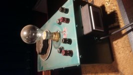
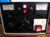
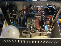
Got mine up and running today. I had one of those solid state relays i picked up a while back so i stuffed it into the enclosure with a switch so i can toggle between it and the classic variac. It seems to work fine, but may be too noisy to use with amplifiers. It is rated for 25amps so who knows it may be useful someday. 1pc Kyotto AC Solid State Relay SSR KR2025AX 280VAC 25A VR to AC | eBay
I also cannibalized my dim bulb tester and built it into the unit. In short i have three switches, one to toggle between the variac and SSR, the second switches between the variacs and direct mains power, it also switches the neutral so the middle "off" position completely disconnects the live and neutral from the output making the equipment under test safe to work on. The third switch then adds the bulb limiter into the circuit. In theory i wont have to mess about plugging and unplugging variacs and bulb limiters as i can do it all with the flick of a switch now 🙂
I also cannibalized my dim bulb tester and built it into the unit. In short i have three switches, one to toggle between the variac and SSR, the second switches between the variacs and direct mains power, it also switches the neutral so the middle "off" position completely disconnects the live and neutral from the output making the equipment under test safe to work on. The third switch then adds the bulb limiter into the circuit. In theory i wont have to mess about plugging and unplugging variacs and bulb limiters as i can do it all with the flick of a switch now 🙂
Attachments
Since a variac is a transformer a ratio thing and the most critical part is the wiper make shure that there is a fuse in the wiper ...
A fuse in the power line will not protec the wiper from damage if you are using the variac with a low output voltage.
If the variac is set to 20% of voltage remenber the way a transformer works you may have an output current 5 times the line current .. a lot more than what is expected at the wiper.
If there a fuse in the wiper it will simply blow..
My Variac (Berco Regavolt) is rated @ 2.75Aac
I have always assumed the wiper can pass that rated current, irrespective of where the tapping point is.
I can see from the graph in the instructions that is there is a small range of output voltages where the maximum current goes up as high as 3.25Aac. The maximum current is specified from 0Vac output to 20% of Vac output and from 80% of Vac output to 112% of Vac output.
@ 50% of Vac output the maximum current equals the rated current of 2.75Aac.
If one is lucky enough to have a 10Aac Variac, then one can draw 10Aac, even when the wiper tapping point is at 20%.
Last edited:
My Variac is rated @ 2.75Aac
I have always assumed the wiper can pass that rated current, irrespective of where the tapping point is.
I can see from the graph in the instructions that is there is a small ranges of output voltages where the maximum current goes up as high as 3.25Aac.
Ok lest start with this.
Now assume the wiper is set at 10% ..output voltage will be 1/10 of input voltage & output current will be 10 times input current. so if output current should not go above 3.25 amp input curent will be 0.32amp.
Then if the wiper is set at 80% ..output voltage will be 8/10 of input voltage & output current will be 1.25 times input current. so if output current should not go above 3.25 amp input current will be 2.6amp.
Output current is should not go above rated current but input current is depandant of the ratio, if you change the ratio maximum output current is still the same but input current will change.
Putting the fuse at the input will protec only one part of the winding but will not protect the wiper.
To protect the wiper ( the most critical part of the variac ) fuse must be in the wiper.
- Status
- Not open for further replies.
- Home
- Design & Build
- Equipment & Tools
- Variac: what should I add when putting it in an enclosure?