Elvee you have difficulty admitting it when you are wrong. In posts #2, #9, and elsewhere you mention VHF but it never appears in your simulations. In post #12 you confidently proclaim that cap-across-rectifier is 60dB quieter than snubbering and you have a simulation which proves it. Except that post #13 showed this to be incorrect. In post #14 you warned of the horrible looming danger of imbalenced bridges causing common mode voltage (gasp!), and in post#17 you triumphantly exhibit a simulation which shows common mode voltage arising from imbalanced diodes. Except that post #19 showed that common mode voltage is inevitable even with the caps-across-diodes approach; now suddenly you are no longer fearful of the horrible danger of common mode voltage.
Often wrong, but never in doubt.
I think the root cause of your errors, and of the error embedded within the "industry standard design in use for 45 years", is the incorrect assumption that diodes are are voltage sources. Your picture attached to post #20 makes this mistake more than a dozen times. I think all of your problems will disappear when you model each diode as a voltage controlled current source as, for example, SPICE does. Then you will realize that the diode switchoff is a current phenomenon. Switchoff creates a large dI/dt; and then noise voltage arises if/when dI/dt is applied to an inductance, producing Vnoise = L * dI/dt. Diodes don't spontaneously emit "sprays of VHF and HF" voltage noise; they merely generate fast-changing current waveforms. If and when the fast changing current stimulates an inductor, that's when problems arise.
If you like, you can connect big capacitors to these inductors, which lowers the natural frequency of the resonant LC circuit, and which lowers its effective impedance Zeff=sqrt(L/C). Since the voltage produced is proportional to effective impedance {Vnoise = Istimulus * Zeff}, reducing effective impedance reduces the magnitude of the voltage noise. Your simulations in post #12 increased the capacitance from 128pF to 10128pF (79X), and the magnitude of the simulated noise fell by sqrt(79) = 8.9X. The next step is to apply textbook standard linear systems theory of RLC circuits, giving critical damping (zeta=1.00 ; Q=0.50). Poof, the oscillation dies immediately. Just like the textbooks predict. No handwaving necessary. It can be simulated.
I have a theory which seems to fit the data: I think that sometime in the 1960's, when the semiconductor industry switched to planar process diodes (with much higher dI/dt than older alloy diodes), previously working radio circuit designs suddenly started buzzing. They built a radio with the old diodes- no buzz. They built another identical copy of the radio except using new diodes- buzz appears! Therefore the buzz must be caused by the diodes! Let's try putting a capacitor across each diode. Eureka! The buzz disappears. And no further analysis was performed. The trial and error "solution" was solemnly passed from generation to generation of radio designers, who slavishly copied it into each radio, and-- it WORKED! Nobody thought to ask, how good is "good enough?" How much better than "good enough" could we make this, if we tried? Naww, let's just defend the status quo.
Mark,
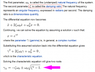
Thanks for making the mechanism clear. However I do have a bone to pick with you! Zeta for damping? When learning this stuff we always looked at the complex Gamma.
<ins>"\gamma_{\pm}=-\zeta \omega_0 \pm \omega_0 \sqrt{\zeta ^2 - 1}."</ins>
Well I screwed up the HTML!
Thanks for making the mechanism clear. However I do have a bone to pick with you! Zeta for damping? When learning this stuff we always looked at the complex Gamma.
<ins>"\gamma_{\pm}=-\zeta \omega_0 \pm \omega_0 \sqrt{\zeta ^2 - 1}."</ins>
Well I screwed up the HTML!
Last edited:
a wise man once said return the noise from whence it came. the diodes themselves have losses to damp the shortened loop areas which is of greater importance for HF. a lot of folks do not consider recovery charge energy to account for.
pick diodes to match their applications, no need for fast power diodes in line frequency apps.
Marks "theory" of industry is quite laughable. in light of FCC conducted EMI/RFI test standards that have been in place for >30 years.
pick diodes to match their applications, no need for fast power diodes in line frequency apps.
Marks "theory" of industry is quite laughable. in light of FCC conducted EMI/RFI test standards that have been in place for >30 years.
Last edited:
a wise man once said return the noise from whence it came. the diodes themselves have losses to damp the shorted loop areas which is of importance for HF. a lot of folks do not consider recovery charge energy to account for.
pick diodes to match their applications, no need for fast power diodes in line frequency apps.
Marks "theory" of industry is quite laughable. in light of FCC conducted EMI/RFI test standards that have been in place for >30 years.
Actually not. There was a new entrant to the diode business and I used to have some samples. Very low cost, quite popular and extremely high switch off noise. That is when the shunt capacitors began to appear in lots of gear. Also when diode switching noise became a real issue. The manufacturer pointed out at that time for those diodes switch off noise was not a specified parameter.
The big problem with shunt capacitors is that they let in line noise for the full cycle. Diodes only let the noise in while conducting.
Now what bothers me is I can no longer find the samples which most likely means they actually got put into a project.
actually yes, this problem has been with the power supply industry (including many "new" semi proposed product lines) for a long time.
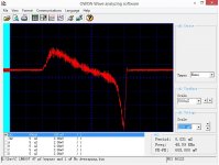
many engineers have dealt with all the tradeoffs over the whole freq spectrum while staring at spectrum analyzers doing what can be seen on many designs such as Elvee shows. This a well worn trodden path to folks in the industry Powercon papers are out there etc
many engineers have dealt with all the tradeoffs over the whole freq spectrum while staring at spectrum analyzers doing what can be seen on many designs such as Elvee shows. This a well worn trodden path to folks in the industry Powercon papers are out there etc
Last edited:
actually yes, this problem has been with the power supply industry (including many "new" semi proposed product lines) for a long time.
many engineers have dealt with all the tradeoffs over the whole freq spectrum while staring at spectrum analyzers doing what can be seen on many designs such as Elvee shows.
As far as I know folks like Corcom started in the mid 1950's. Most folks then were putting a pair of capacitors from each side of the AC line to the chassis to prevent EMI issues. Then it was mostly pickup from local AM broadcast stations. FM broadcasting although started earlier moved up to the current band when Television began commercial service in 1941.
So until the late 1950's EMI wasn't much of an issue as there were few sources or receivers. (When examining noise one looks at the source, path and receiver.)
I gather you weren't around in the mid 50's.
haha what gave it awayI gather you weren't around in the mid 50's.
no but I have seen much in my life, for example starting in JR High shop class one of my teachers was paid to train us kids to repair old fashioned cheap AC/DC tabletop radios including car radios with tubes / mechanical switchers. Midway in my career I was designing fast frequency LO's or radio freq. sources for satcom and VHF/UHF transceivers/ modems.
haha what gave it away
no but I have seen much in my life, for example starting in JR High shop class one of my teachers was paid to train us kids to repair old fashioned cheap AC/DC tabletop radios including car radios with tubes / mechanical switchers. Midway in my career I was designing fast frequency LO's or radio freq. sources for satcom and VHF/UHF transceivers/ modems.
Satcom? You mean the much ado about Telstar is over? What you didn't go outside to watch "Echo" float around the globe?
I used to fix the "All American Five" AM radios for a bit of side money.
Now I am not old enough to ever have seen a rotary synchronous rectifier. But I have seen lots of vibrator power supplies.
The first semiconductor rectifiers were stacked selenium plates. In the early 1950's General Electric introduced the first metal can power rectifiers 1N9xs. Germanium but good for a few hundred volts!
Shortly there after silicon appeared. The first ones I saw were actually used in light switches to give a High-Low-Off dimmer.
Now if we want to continue the bit about snubbers we could look at old schematics and see when they first appeared.
haha I rather talk about the education system, I often wonder about my disabled shop teacher and why the school district thought it was a good idea to train folks on a technology that was in the last twilight. I was into Milstar doomsday scenes from the scifi channel, but since I and it was never declassified so id probably have to kill ya. LOL
the 1st snubber IDK probably Telsa designs?
I remember on some SMPS designs they had a "snubber power budget" to meet efficiency and ripple / EMI specs.
one old timer said filtering EMI was like pushing on a water balloon, squeeze on one side and it pops out of another.
the 1st snubber IDK probably Telsa designs?
I remember on some SMPS designs they had a "snubber power budget" to meet efficiency and ripple / EMI specs.
one old timer said filtering EMI was like pushing on a water balloon, squeeze on one side and it pops out of another.
Last edited:
When learning this stuff we always looked at the complex Gamma
Hi Ed. Informally speaking, complex gamma is the log of the pole location(s). (formally, Pole = exp(gamma * t)). The real number zeta is just the damping ratio. As you showed, the pole locations are functions of the damping ratio and the natural frequency omega_naught.
Here is the relevant piece of the Wikipedia article
_

Attachments
model each diode as a voltage controlled current source as, for example, SPICE does. Then you will realize that the diode switchoff is a current phenomenon. Switchoff creates a large dI/dt; and then noise voltage arises if/when dI/dt is applied to an inductance, producing Vnoise = L * dI/dt. Diodes don't spontaneously emit "sprays of VHF and HF" voltage noise; they merely generate fast-changing current waveforms. If and when the fast changing current stimulates an inductor, that's when problems arise.
This explains why ferrite beads are placed on HF rectifiers. Any mention of why they are there is usually just a note saying to reduce noise. But now i understand the underlying cause.
Maybe you forgot this one?Elvee you have difficulty admitting it when you are wrong. In posts #2, #9, and elsewhere you mention VHF but it never appears in your simulations.
Yet you claimed to have solved it better than with the simple parallel cap; in spice, at least, in the real world it could be trickier:
In post #12 you confidently proclaim that cap-across-rectifier is 60dB quieter than snubbering and you have a simulation which proves it. Except that post #13 showed this to be incorrect.
I think there is a basic misunderstanding between us: you are concerned with the large amplitude, nasty looking ringing of moderately high frequency. You look at it in the time-domain, and when things look perfectly clean, you declare the problem solved.In post #14 you warned of the horrible looming danger of imbalenced bridges causing common mode voltage (gasp!), and in post#17 you triumphantly exhibit a simulation which shows common mode voltage arising from imbalanced diodes. Except that post #19 showed that common mode voltage is inevitable even with the caps-across-diodes approach; now suddenly you are no longer fearful of the horrible danger of common mode voltage.
For my part, I don't deny the presence of the ringing, but I feel only moderately concerned by it, because in general I find it easily manageable.
I am more concerned by the higher frequency components, of much smaller amplitude that hide in the big bad waveform, because they are much more difficult to trace, and once you let them out of the box (the diode), controlling them becomes much more difficult.
A diode is many things at the same time: depending on the where in the cycle you look, it can be a resistance (non-linear), a capacitance, a current source and a voltage source. Note that for my explanations, you could make a Thevenin/Norton transformation, it is equally valid.I think the root cause of your errors, and of the error embedded within the "industry standard design in use for 45 years", is the incorrect assumption that diodes are are voltage sources. Your picture attached to post #20 makes this mistake more than a dozen times. I think all of your problems will disappear when you model each diode as a voltage controlled current source as, for example, SPICE does
The simplistic, textbook model of a voltage-controlled current source covers 99.9% of the behavior, but the most problematic part sits in the remaining 0.1% (or 0.01%), and that is the reason why I preferred to model the noise as a voltage.
In fact, during the reverse recovery phase, the diode has all the attribute of a voltage source, to the extent that it can actually supply energy to the outside world, without external bias or anything.
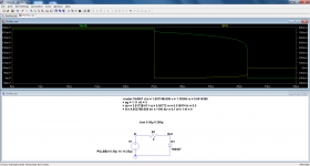
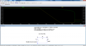
Since you're a fan of spice sims, I will illustrate that with a small sim, I think it will make matters much clearer.
The circuit applies a forward current of ~800mA for 25µs to the diode via a 4Ω resistor. Then, the source is turned off, leaving in fact the 4Ω in parallel with the diode.
You can see that at the switching instant, the voltage across the diode does practically not change, except for a small step: the diode is now actively delivering energy to the resistor, and it is very different from a capacitive discharge, because the voltage stays almost at the same level for a plateau of ~16µs.
The amplitude of the small initial step is ~43mV, and the Δi is 800-(-200)= 1A.
Thus, for all the recovery period, the diode behaves like a ~800mV battery, and an incredibly stiff one because its internal resistance is 43mΩ.
This undoubtedly makes it a voltage source.
So far, it is a rather innocuous one, it is simply a DC source that will not generate interference.
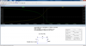
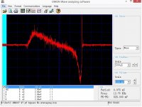
When the plateau ends, interesting things begin to happen: the second pic shows a zoom of that instant.
When all of the stored charge have been exhausted, the voltage (and thus the current in the load) collapses with an extreme brutality: the slew-rate reaches 370V/µs, yet the absolute value of the variation is small, a few hundred mV.
It is at that instant that a spray of RF is emitted.
This is only a sim, and honestly I think that the magnitude of the phenomenon is too extreme. I have seen some pathological stinkers in the past, but I don't think you would find something as bad in the current production.
But basically, this is a reflection of the reality, and if you test a diode in this way, you will typically see this kind of profile, just less nasty.
With a function generator having a 50Ω output, you can easily reproduce a smaller scale version of the test: there will be some difference, but the general outlook will be the same
Of course, this is just a test, under pulse conditions, and it doesn't quite reflect the reality of a 50/60Hz rectifier.
You might also object that what you see is a result of the stimulus being too fast: the transition time is 1ns.
In reality, this is not the case: if the transition time is increased to 15µs, the final collapse remains as nasty: this means that the noise source is completely autonomous, just like an independent step generator
Obviously, if the slew rate of the stimulus is decreased much further, things will calm down at some point, but there will always be a small residue of HF: it will have a much lower amplitude and will be hidden in the low frequency waveform, but it will be present.
To combat such a phenomenon, the only practical option is to kill it at the source: if you carry it through tracks, wires or filter capacitors, some of it will be radiated and propagate further.
Note that in a transformer+rectifier+cap supply, the di/dt during the charging pulses can be quite significant if the cap is large and low esr, and the transformer has a low leakage inductance, as in a toroidal.
There may be a bit of that, but ordinary rectifier diodes are not planar.I have a theory which seems to fit the data: I think that sometime in the 1960's, when the semiconductor industry switched to planar process diodes (with much higher dI/dt than older alloy diodes), previously working radio circuit designs suddenly started buzzing. They built a radio with the old diodes- no buzz. They built another identical copy of the radio except using new diodes- buzz appears! Therefore the buzz must be caused by the diodes! Let's try putting a capacitor across each diode. Eureka! The buzz disappears. And no further analysis was performed. The trial and error "solution" was solemnly passed from generation to generation of radio designers, who slavishly copied it into each radio, and-- it WORKED! Nobody thought to ask, how good is "good enough?" How much better than "good enough" could we make this, if we tried? Naww, let's just defend the status quo.
I am sure the processes have improved (mostly), but modern diodes still show the kind of recovery behavior I have illustrated, and this can easily be verified.
Attachments
Elvee, you have tried twice to present simulations showing shunt-capacitors-across-diodes performing better than snubber-across-transformer. Both times you failed. Your halfwave rectifier simulation showed that CRC snubber gave smaller FFT artifacts and smaller time domain amplitude, than shunt-caps-across-diodes. Your fullwave rectifier simulation showed that both approaches produce common mode voltage because mismatched diodes / mismatched capacitors are inevitable. Neither circuit is best.
Would you like to try a third time? Would you like to present a SPICE simulation which shows shunt-caps-across-diodes clearly and obviously outperforming snubber-across-transformer-secondary?
Or perhaps this simply cannot be shown in simulation? SPICE is not up to the task?
Would you like to try a third time? Would you like to present a SPICE simulation which shows shunt-caps-across-diodes clearly and obviously outperforming snubber-across-transformer-secondary?
Or perhaps this simply cannot be shown in simulation? SPICE is not up to the task?
No, because it is perfectly obvious that it would be a pointless exercise: you are certainly not going to move, and the nitpicking could go on for ever.Would you like to try a third time?
If other members want to form their opinion, I think they have enough elements from both sides to decide for themselves
My take on it.
Elvee method, lowest cost, good enough. Use on production runs of consumer equipment were every penny counts.
Johnson method, best performance, safest. Use on high end equipment or limited production.
Elvee method, lowest cost, good enough. Use on production runs of consumer equipment were every penny counts.
Johnson method, best performance, safest. Use on high end equipment or limited production.
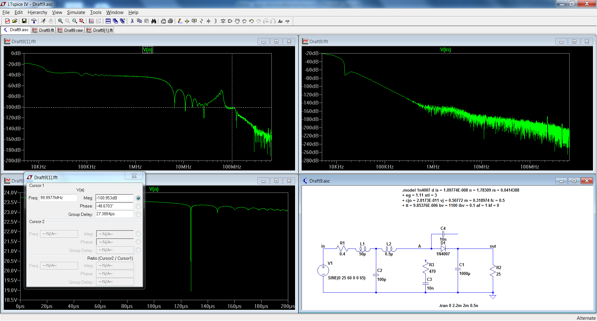
Okay, Elvee, if you change your mind and create a third simulation comparison I would love to see it.
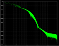
Meanwhile I got curious about your second transient waveform plot (common mode voltage, A&B) in post #17. Visually it appeared that those 60Hz waveforms were smooth and slow moving, but I wondered whether there might be some snap-recovery fast behavior buried inside. It was fun to learn how to nudge LTSPICE into making an FFT plot of a waveform arithmetic expression "(V(A)+V(B))/2" ! Finally I got the FFT displayed below. Not much is happening above 6 kHz.
_
Attachments
Powerbob, judging by the ultra nosebleed high end preamp designs of John Curl, that segment of the market applies all possible countermeasures in each piece of equipment. Curl's preamps, for example, include all of these:
- IEC power inlet with embedded EMI/RFI filter (example)
- Rcore transformer for lowest primary-to-secondary capacitance
- Secondary snubber operated at critical damping (zeta=1.0)
- Common mode choke (example)
- Choke snubber operated at critical damping
- Soft recovery diodes for smallest possible dI/dt injection (measurement data)
- Pi filtering between diodes and voltage regulator
Last edited:
Here are actual results of 1N4007 diodes.
Notice in the first one how much line noise is let in during conduction.
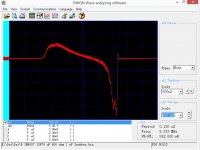
The second has on diode snubber caps. Noise down due to scope averaging! (Probably just confusing as it is the same as the first!)
The last use transformer and diode snubbers.
The line noise was increase by a buzzer powered through a step down transformer.
Mark,
We just gotta keep disagreeing. John Curl also places a 10 uF capacitor across the AC line for his good preamps.
Notice in the first one how much line noise is let in during conduction.
The second has on diode snubber caps. Noise down due to scope averaging! (Probably just confusing as it is the same as the first!)
The last use transformer and diode snubbers.
The line noise was increase by a buzzer powered through a step down transformer.
Mark,
We just gotta keep disagreeing. John Curl also places a 10 uF capacitor across the AC line for his good preamps.
Attachments
Last edited:
Wow! Ten microfarads from 115VAC Line to 115VAC Neutral?? That would need to be an X2 safety rated capacitor, and the cheapest one I could find in 90 seconds of searching, costs about three dollars in quantity 100 (link).John Curl also places a 10 uF capacitor across the AC line for his good preamps.
I wonder whether he could save himself some money by installing a large diameter, heavy, Metal Oxide Varistor (or bidirectional TVS!) instead. Those things have astoundingly high capacitance. He'd get the capacitance he wants, and a dollop of surge protection too.
- Status
- Not open for further replies.
- Home
- Amplifiers
- Power Supplies
- Rectifier Diode Snubber;