Hi there
Someone probably has already had this idea: it looks too obvious.
Anyway, here is my proposition:
Tube OPT's are notoriously difficult to make, because they need to fulfill many contradictory requirements at the same time.
Life would be much easier if the task could be divided between two specialized transformers: a low frequency one, having a good primary inductance and a good V*s capacity, and a high frequency one having a low leakage inductance and a low capacitance (based on ferrite cores for example).
This looks simple and obvious, but is in reality fiendishly difficult: all the magnetizing, leakage and crossover-filter inductances have a multitude of resonances possible with the crossover capacitances, making the composite frequency response a nightmare of peaks and troughs.
By sufficiently damping all the reactive elements, flattening would be possible, but at the expense of 10dB output power or so.
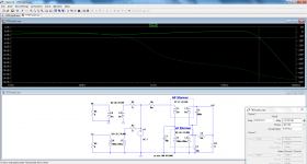
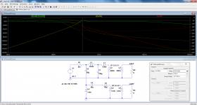
Here is a topology that doesn't require additional damping, and yet offers a reasonably flat FR.
In this example, the impedances are normalized to the secondary for simplicity.
The two transformers have pretty lax parameters, and are thus easy to manufacture, yet the global FR remains flat to about 30KHz.
Of course, this is only one of an infinity of tradeoffs possible, and I am sure this can be improved on many counts, but it gives a first taste of the technique.
Since transformers primaries are in series, the method would be useable for simple PP or SE outputs indifferently.
For more complicated arrangements, like UL some more thinking would be required, but an adaptation is probably possible.
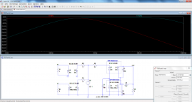
The second pic shows the FR of the individual transformers with the nominal load as source impedance.
The composite is shown with zero source impedance, because it is the most challenging (no input damping).
Opinions, ideas?
Someone probably has already had this idea: it looks too obvious.
Anyway, here is my proposition:
Tube OPT's are notoriously difficult to make, because they need to fulfill many contradictory requirements at the same time.
Life would be much easier if the task could be divided between two specialized transformers: a low frequency one, having a good primary inductance and a good V*s capacity, and a high frequency one having a low leakage inductance and a low capacitance (based on ferrite cores for example).
This looks simple and obvious, but is in reality fiendishly difficult: all the magnetizing, leakage and crossover-filter inductances have a multitude of resonances possible with the crossover capacitances, making the composite frequency response a nightmare of peaks and troughs.
By sufficiently damping all the reactive elements, flattening would be possible, but at the expense of 10dB output power or so.
Here is a topology that doesn't require additional damping, and yet offers a reasonably flat FR.
In this example, the impedances are normalized to the secondary for simplicity.
The two transformers have pretty lax parameters, and are thus easy to manufacture, yet the global FR remains flat to about 30KHz.
Of course, this is only one of an infinity of tradeoffs possible, and I am sure this can be improved on many counts, but it gives a first taste of the technique.
Since transformers primaries are in series, the method would be useable for simple PP or SE outputs indifferently.
For more complicated arrangements, like UL some more thinking would be required, but an adaptation is probably possible.
The second pic shows the FR of the individual transformers with the nominal load as source impedance.
The composite is shown with zero source impedance, because it is the most challenging (no input damping).
Opinions, ideas?
Attachments

If I understand it correctly, you are combining the output of the two transformers? Why not design the cross-over and transformers, so that the LF transformer only supplies the woofer, while the HF transformer only supplies the tweeter?
That would be a possibility, but probably not general enough to satisfy everyone, and you would still have to put a crossover in front of the transformers, which in theory should be easier than the Xover+combiner, because less resonances are possible, but I would be cautious, and you would need to examine carefully the phases of the outputs, to make sure the recombination at the acoustic level doesn't result in unwanted artifacts.If I understand it correctly, you are combining the output of the two transformers? Why not design the cross-over and transformers, so that the LF transformer only supplies the woofer, while the HF transformer only supplies the tweeter?
It is a certainly an alley worth exploring too.

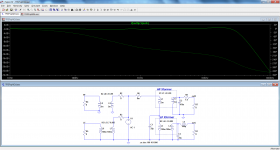
Making this adaptation was quite easy, and resulted in an even flatter composite output than with an electrical combiner.Why not design the cross-over and transformers, so that the LF transformer only supplies the woofer, while the HF transformer only supplies the tweeter?
What is required is the phase inversion of one of the transformers, and minor value tweaks:
Attachments
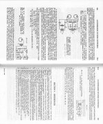
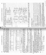
RDH 4th ed. has it all worked out:
Since one can get cheap TV tubes, one would be better off splitting the bands BEFORE two output stages (using the same B+ supply) and just using those OT outputs to run the tweeter and woofer (without re-combining). At low signal level, simple RC filters could be used. The problem is still where to get a LF OT.
If you put MosFets on the LF channel side, and tubes on the HF side, then some AC power toroids or industrial E-I xfmrs could be used for the LF OT. Maybe could get Edcor to make an XSM 10K/8 ($14) for the HF band.
Attachments
Last edited:
Hmmm, since the Edcor XSM xfmrs are spec'd down to 20 Hz already,
to use it above say 300 Hz only, one would want an XSM 1000/0.8 model or similar. That would become 10K/8 at 200 Hz, and would handle 10X the power above 200 Hz, compared to 20 Hz. (so 25 Watt then) ($14)
Ahh, there IS an XPP15-4-5K rated 70 Hz to 18KHz for 15 Watts,
which would be equivalent to XPP30-8-10K for 140 Hz to 18 KHz for 30 Watts. ($21.45)
There's also an XPP25-4-7.6K for 25 Watts which would translate to XPP50-8-15.2K for 50 Watts above 140 Hz. ($23.05)
None of the GXPP OTs are making any sense at $39,
might as well pay $10 more for a CXPP25 and be done with the whole thing (20Hz to 20KHz).
Last edited:
Thanks. I suspected it had already been tried, but I wasn't able to find anything.RDH 4th ed. has it all worked out:.
Thanks for sharing this Elvee - I'd been thinking about combining the outputs of two amps (classD on bass and classAB on mid/top ) but hadn't gone much further than mere contemplation. Seeing your thread has provided further impetus to pursue the notion.
This one looks more like my version, with the primaries in series
That is something I contemplated too, but for semiconductors I think a current-dumping style scheme would be more appropriate: you do not need or want the inconvenience of transformers. For tubes, they are practically a necessity.Thanks for sharing this Elvee - I'd been thinking about combining the outputs of two amps (classD on bass and classAB on mid/top ) but hadn't gone much further than mere contemplation. Seeing your thread has provided further impetus to pursue the notion.
I have simulated the RDH version, after normalizing it to 8 ohm; it does work, but the results are a bit disappointing: whatever the output phases, there is a large (or larger) dip at around the Xover frequency.
Maybe the acoustics are supposed to for correct this?
With a zero source impedance, things get worse, logically: there is now also a bump.
In principle, a tube output stage is not supposed to have ~0 output impedance, but since it is impossible to apply global feedback because of the two separate outputs, maybe there is a feedback at the primary level which would reduce the apparent impedance?
More probably, it is supposed to operate completely open-loop.
With a high impedance drive, things look even worse, thus it is probably intended for triodes, without any feedback.
In the end, the version I proposed comes out better: it is flatter, uses less inductive components, and allows an electrical composite output too.
Attachments


Magnavox did a 2.1 system back in the day. I have one chassis on the shelf at home with one channel blown. The bass transformer is larger than the two mid/high channel transformers, which are quite small.
That is something I contemplated too, but for semiconductors I think a current-dumping style scheme would be more appropriate: you do not need or want the inconvenience of transformers.
Subjectively I've found the dynamics improve by including trafos. So I for one do want them, at least until I am sure of the reason for this and learn how to design around it (get the same subjective result) with semiconductors. McIntosh have about the only semiconductor amps with (auto)trafos in the output, they also have a good reputation subjectively for dynamics.
- Status
- Not open for further replies.
- Home
- Amplifiers
- Tubes / Valves
- Splitting the audio band into two transformers