Hi,
I need your opinion about an unknown valve output transformer from the sixties (grundig 9060-100-02) taken out from an undetermined radio. According to the usual colour code used by that time, I assumed the red (B+) and blue (anode) to be the primary (the yellow probably being a suppressor grid tap).
The attached file has the description as accurate as I can (sorry for the terrible drawing skills...).
I usually characterize an unknown transformer by injecting a known AC voltage in one of the windings, reading the induced voltages on the other windings and calculating the turn ratios (and impedance ratios) between them. The results for this transformer are as follows:
Apply 230VAC to primary (red-blue wires)
Read 61V from sec1 (black-green1 wires) and 64V from sec2 (brown-green2 wires)
Turn ratio for secondary 1 (black-green1 wires) N=230/61=3,8; Z1 = N2 = 3,9x3,9 = 14,2
Turn ratio for secondary 2 (brown-green2 wires) N=230/64=3,6; Z2 = N2 = 3,6x3,6 = 12,9
As you can see this is not what I would call a standard output transformer because the turn ratios are too low (1:3.8 and 1:3.6 for the first and second secondaries respectively) instead of the typical value for EL84 output transformers (turn ratio around 40).
Any ideas of what this is all about? Am I thinking straight or am I missing something? Are these really output transformers or some sort of interstage ones? Any help would be greatly appreciated!
Thanks to all,
Renato
Attachments
Last edited:
This animal had 8 Loudspeakers, 4 of which were Electrostats which require high voltages;
the other 4 speakers were series connected, so also wired for high v; outputs were indeed EL84 in push-pull, you should have something like a center-tapped winding though ... and a couple more wires on the secondary, too ...
here's a link:
9060W/3D PW+TB Radio Grundig Radio-Vertrieb, RVF, Radiowerke
I have no better resolution but maybe it gives you an idea of the OPT ...
the red and blue went to the anodes of the EL84's, the center tap missing in your sketch should be a pink (?) wire which went to B+
the yellow was connected to the electrostats via capacitors ...
Attachments
Last edited:
Payloadde,
Thank you for your reply!
However there seems to be a misunderstanding coming from my somewhat unclear info: "9060" is the transformer's reference number (in fact 9060-100.02), not the radio model. Plenty of Grundig's transformers have such a reference (the "60" from 9060 being the core size, i.e., EI60 on this case).
Also, the schematic is too small to be perceptible but one thing is clear: there are plenty of taps in such PP transformers but not on this one (and there never were because there are no vestiges of broken leads).
This transformer shares many similarities to single ended transformers, the only mystery being the low turn rates and the presence of two almost similar secondary windings (perceptible because of the wire gauge) and, therefore, the usage.
Can someone shed some light on this? Has someone had experience with such transformers?
Thank you!
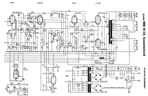
Hello Renato ,
I think , this circuit diagram declares most of your questions . The tap is used as a choke for the power supply , one of the low ohm windings is for the 4 ? ohm loudspeaker , the other is for feedback .
Kind regards , Alexander .
http://www.bilder-hochladen.net/files/big/frgu-1.png
I think , this circuit diagram declares most of your questions . The tap is used as a choke for the power supply , one of the low ohm windings is for the 4 ? ohm loudspeaker , the other is for feedback .
Kind regards , Alexander .
http://www.bilder-hochladen.net/files/big/frgu-1.png
Thank you, Alexander!
The thing that doesn't make sense in this transformer is the turn rate (N) and, consequently, the impedance rate (Z, which equals N squared).
For EL 84s you need a load impedance of arround 5 to 7KOhms.
If you connect this transformer to a 4Ohm speaker, the resulting primary impedance equals 4Ohms times the transformer's impedance ratio which, in this case, is around 15 (N=3.9; Z=NxN=15,2).
So, on this case, with a 4Ohm speaker the output valve sees 4x15=61Ohms. Yes, you're right: SIXTY Ohms. Do you know any valve you could use in a 'standard' output stage with such a load? That's about one hundredth of what it was supposed to be in a SE output stage with EL84s. Hence my doubts.
The way to squeeze 6KOhms out of this strange transformer is by connecting it to a 400Ohm speaker; Does such a thing even exist?
I really need some light here (or am I seeing things wrongly?)
Thank you all for your comments,
Renato
Sorry but I'd forget that transformer and get the proper one for any project I'm interested into.
Why spend time and good money just to use something you found?
Something weird , with no visible application, of course.
DC resistance is compatible with plate and speaker windings but turns ratio is not, at all.
750:1 DCR ratio would be about expected in, say, 7k:8 ohms , so please measure again, multimeter probes straight to secondary wires, which are taped to a piece of wood so they don't wander around and proper contact is easier to make.
DCR ratio roughly following impedance ratio is good practice, simply because it evenly distributes resistive loss between primary and secondary and gets best use of copper (expensive) and window space (scarce), so nobody strays way too far from that.
And if possible try to save your drawing as a .gif or .png or worst case, .jpg which is directly visible inside the post, instead of a .pdf which requires Adobe Acrobat .
Sorry but I'd forget that transformer and get the proper one for any project I'm interested into.
You're absolutely right there. The thing here is more curiosity than finding a use for the damned thing. That and proving the seller to be wrong in describing the item as 'EL84 OPT' (it was not 'found'; I paid for it).
They (the pair) will probably end up their days as chokes because they have huge inductances (20H).
Nevertheless I would love to find out what this is and the original usage. Never thought it would be such a daunting task but I suspect that people with such old knowledge must be scarce these days...
Thanks anyhow!
I have a pair of very similar transformers allegedly from a Blaupunkt radio stereogram. I have been trying to figure out how to use them as output transformers as well. I was sold them as having ultralinear connections but the primary windings don't seem to be in the correct ratio for this application. It is a shame to consign them to the junk box! I guess hunt is on for high impedance speakers to use these.
Just had a thought, a series wired line array would up the speaker resistence pretty quickly?
Just had a thought, a series wired line array would up the speaker resistence pretty quickly?
Last edited:
Yes, they do. Look for Philips AD3800AM speakers.The way to squeeze 6KOhms out of this strange transformer is by connecting it to a 400Ohm speaker; Does such a thing even exist?
The choke inducing the primary has different effects.
First the B+ current flowing opposed to the anode current. That would prehibit core saturation of the economic SE OPT.
Second there will be an opposed 100Hz signal (plus harmonics) to the audio signal. Was that compensated for with the FB winding?
I still think there was some mistesting involved.
Either turns ratio is not 4:1 or DCR ratio is not 700:1 , one of them is an error .
I commercially design and wind transformers and those numbers simply do not match.
Copper wire is made out of copper and follows known Physics rules.
Either turns ratio is not 4:1 or DCR ratio is not 700:1 , one of them is an error .
I commercially design and wind transformers and those numbers simply do not match.
Copper wire is made out of copper and follows known Physics rules.
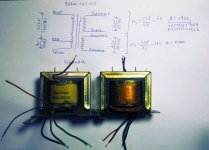
Hi all!
Thank you for your comments. Unfortunately only now could I find time to re-measure my values (thank you for the cue Fahey!) and I reached the conclusion the first ones were... totally wrong. 😱
So I apologize for misleading all of you and I try to make amendments by posting the correct readings, this time (sorry for the handwriting).
As it turns out, the transformer has a secondary winding which is pretty standard for a single-ended output stage (impedance ratio of, about, 1:1900, thus transforming a 4Ohm speaker in a 7,5K Ohm load).
Thank you all for your cooperation and keep helping guys like me (show them the light!).
Greetings to all,
Renato
Attachments
Cool and nice to know, specially that now you'll be able to use that transformer in some standard project, instead of needing an 800 ohms speakers or whatever.
As of the mystery secondary, don't think it's a 2 ohms or 1 ohm speaker out to be used by itself, but an extra winding which in series and proper phase with the existing 4 ohms one, turns the combination into an eight ohms one or thereabouts.
Remember thatgoing from 4 to 8 ohms secondary, you don't need another 10% or turns, but only 41% more.
If used alone, of course it would show a very low impedance, way below 4 ohms.
You may repeat the calculations with both in series and recalculate impedance for the whole secondary.
Start with ~7k primary impedance and see what you find in the full secondary, which will be more than 4 ohms but less than 16 ohms (which would require 2 equal secondary windings, not the case here).
- Status
- Not open for further replies.
- Home
- Amplifiers
- Tubes / Valves
- Grundig 9060 output transformer identifying