Similarly I have a CD50. To do this I would use surface mount capacitors
The one I have was a breeze to do. I used 0603 size components.
Obtain a magnifying lamp or magnifier glasses, as they really help.
Cheers / Chris
The one I have was a breeze to do. I used 0603 size components.
Obtain a magnifying lamp or magnifier glasses, as they really help.
Cheers / Chris
Thank you Sound happy , I shall look over the tracks, also in your previous reply, yes i cut those 2 other traces near the chip. I was actually following svilen to do the nos, so maybe error is in the PSUHi MaccAu
Do you have cut two other pcb copper tracks ?
Greetings
Similarly I have a CD50. To do this I would use surface mount capacitors
The one I have was a breeze to do. I used 0603 size components.
Obtain a magnifying lamp or magnifier glasses, as they really help.
Cheers / Chris
Hi Chris Thank you for the reply. I have free shipping with Element14 atm, see if I can obtain a magnifying lamp, as I have to keep taking photos and running back to the pc to check 0603 wimas?
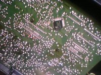
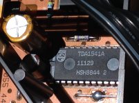
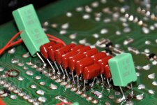
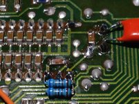
Here is an image, showing how 0603 caps are stacked on top of existing TDA1541
caps. with a job like this it pays to use a tiny dot of super glue to position
the cap on top of the existing one prior to soldering.
if original caps have been removed, you are best starting with appropriate capacitance
values in 1206 size. but if the original 1206's are there 0603 or 0805
will do a good job. With 0603 solder needs to roll up each side, so placement
in the middle of the existing 1206 is needed, 0805 will be slightly easier if
stacking on top of originals.
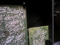
Second image shows a bit closer
Cheers / Chris.
caps. with a job like this it pays to use a tiny dot of super glue to position
the cap on top of the existing one prior to soldering.
if original caps have been removed, you are best starting with appropriate capacitance
values in 1206 size. but if the original 1206's are there 0603 or 0805
will do a good job. With 0603 solder needs to roll up each side, so placement
in the middle of the existing 1206 is needed, 0805 will be slightly easier if
stacking on top of originals.
Second image shows a bit closer
Cheers / Chris.
Attachments
Last edited:
Thank you Sound happy , I shall look over the tracks, also in your previous reply, yes i cut those 2 other traces near the chip. I was actually following svilen to do the nos, so maybe error is in the PSU
Hi MaccAu
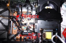
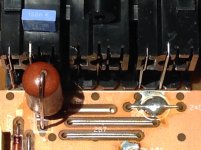
One electrolitics are not in right position reverse (-) of capacitor on square dot side like others on pcb are ok. And another question do you put off one green capacitor ? Normaly this is BP bipolar cap ( not polarised ) so we can't change with polarised (-)(+).
Bring this bipolar cap back on the same place.
http://lampizator.eu/LAMPIZATOR/REFERENCES/MARANTZ_CD50/CD50_marantz.html
Hope it's help
Greetings 🙂
Attachments
Last edited:
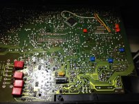
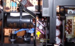
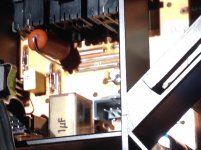
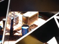
This is my CD50 Marantz photos.
I change to Fine Gold and Silmic II in audio path and new industrial BC components capacitors in not critical points.
Sound is nice but great step to high fidelity are transformation of op-amp's section or better solution not op-amp´s at all
just direct connection of 1541 DAC to class A tube buffer stage with his own PSU that is the way i go 🙂
Attachments
Hi MaccAu
One electrolitics are not in right position reverse (-) of capacitor on square dot side like others on pcb are ok. And another question do you put off one green capacitor ? Normaly this is BP bipolar cap ( not polarised ) so we can't change with polarised (-)(+).
Bring this bipolar cap back on the same place.
CD50_marantz
Hope it's help
Greetings 🙂
Greetings Soundhappy 🙂
Yes i found this fault this morning, wrong direction near IC , feel stupid, but I guess mistakes happen, IF i am lucky this will fix problem, fix it and report back , i have 2 marantz CD50, i bought one years ago with Lampizator nos
work, the output caps, the seller used non polar. ( + - - +) SilmicII. If buzz continues, will get more BPmuse, i have 100uf 35v in stock
Thanks so much for the help, wrong direction of cap maybe caused buzz sound.
This is my CD50 Marantz photos.
I change to Fine Gold and Silmic II in audio path and new industrial BC components capacitors in not critical points.
Sound is nice but great step to high fidelity are transformation of op-amp's section or better solution not op-amp´s at all
just direct connection of 1541 DAC to class A tube buffer stage with his own PSU that is the way i go 🙂
Very nice mods, yes woud be good to bypass opamp, Lampizator does that with all his mods mostly. From your picture I can see the cap direction around the DAC, just like my bought CD50, my modded cd50 I have the direction wrong, please hope this is the fault😀
thanks
Sam🙂
Here is an image, showing how 0603 caps are stacked on top of existing TDA1541
caps. with a job like this it pays to use a tiny dot of super glue to position
the cap on top of the existing one prior to soldering.
if original caps have been removed, you are best starting with appropriate capacitance
values in 1206 size. but if the original 1206's are there 0603 or 0805
will do a good job. With 0603 solder needs to roll up each side, so placement
in the middle of the existing 1206 is needed, 0805 will be slightly easier if
stacking on top of originals.
Second image shows a bit closer
Cheers / Chris.
Hi Chris
Thanks for the tips with the smds and picture. Silly me reverved a cap, just found this morning comparing my 2 CD50s side by side😱
Very nice mods, yes woud be good to bypass opamp, Lampizator does that with all his mods mostly. From your picture I can see the cap direction around the DAC, just like my bought CD50, my modded cd50 I have the direction wrong, please hope this is the fault😀
thanks
Sam🙂
Hi Sam
Yes CD50 is funny diy project. I must try this tube buffer but for this evening
i change 100 nF MKT cap connected with signal output RCA to similar
but vintage cap and bypased with 0,1 uF styroflex on other side with 39k smd resistance.
Tested on song with woman who have not natural " sssssss " on his voice
https://www.youtube.com/watch?v=RjqlLgycDRs
and now is better for my ears " more acoustic " feeling.
I need decoupling all TDA1451A pins as well
Short conclusion at this step: sound nice but is not sonic revolution.
New low jitter clock and tube buffer all with his own psu can transform
much more in direction to amazing vintage cd player haha !
😀
Attachments
Nice work from both of you.
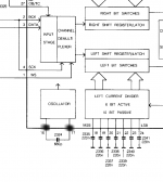
Now you can try moding. do the DEM clock mod that should give you smooth presentation,more attack and details. its only 2x 6K8 resistor from -15V to dem pins.
Now you can try moding. do the DEM clock mod that should give you smooth presentation,more attack and details. its only 2x 6K8 resistor from -15V to dem pins.
Nice work from both of you.
Now you can try moding. do the DEM clock mod that should give you smooth presentation,more attack and details. its only 2x 6K8 resistor from -15V to dem pins.
Hi Danico
Nice thanks 🙂
Interesting DEM clock mod but which precise pins of demodulator ?
Any photos , link or small schematic ? I be very appreciated.
Greetings
Nice work Soundhappy.
I noticed you used resistor? on the output? and bypass films on power capacitor around the dac and opamp caps. I like the sound she has good vocals 🙂
changing the cap around i still getting buzzing, the first day i did mod i left player on 20minutes and no sound. I am worried if TDA is shorted and dead 🙁
maybe no enough power using 220uf 25v around dac
Hi Danicon
Nice clock that would be good, though still issues with player buzzing
I noticed you used resistor? on the output? and bypass films on power capacitor around the dac and opamp caps. I like the sound she has good vocals 🙂
changing the cap around i still getting buzzing, the first day i did mod i left player on 20minutes and no sound. I am worried if TDA is shorted and dead 🙁
An externally hosted image should be here but it was not working when we last tested it.
An externally hosted image should be here but it was not working when we last tested it.
An externally hosted image should be here but it was not working when we last tested it.
maybe no enough power using 220uf 25v around dac
Hi Danicon
Nice clock that would be good, though still issues with player buzzing
Last edited:
Hey Soundhappy,
The two resistor goes to the pin 16 and 17 from -15V. (that is where the 680pf cap is. 6K8 Ohm should work .
top traces left to right without resistors with right with music playing.
bottom traces with the resistor in place. less noise= better music
The two resistor goes to the pin 16 and 17 from -15V. (that is where the 680pf cap is. 6K8 Ohm should work .
top traces left to right without resistors with right with music playing.
bottom traces with the resistor in place. less noise= better music
Attachments

220uf more then enough. actually I prefer the smaller size like 47uf.
bigger caps just slows the music down.
Your soldering improved a lot. clean and nice.
I hope you will find the cause of the buzz.
bigger caps just slows the music down.
Your soldering improved a lot. clean and nice.
I hope you will find the cause of the buzz.
Last edited:
Hi MaccAu et Danico
You are great guys !
Thanks for schematic Danico i try modify quickly 😀
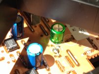
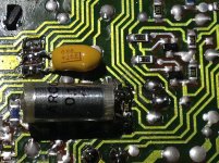
@ MaccAu this is capacitor not resistor but shape are similar 😀
I was wrong about capacitor this one are bypass not connected to rca .
Rca are muse greens nichicons 100 uF / 16 V bipolars. One question :
do you have 5 electrochemicals + 1 non polarized in this place see on photo nothig missing ?
Maybe one close to diodes ?
I find photo with perfect bypass made but is not my 😉
Greetings
You are great guys !
Thanks for schematic Danico i try modify quickly 😀
@ MaccAu this is capacitor not resistor but shape are similar 😀
I was wrong about capacitor this one are bypass not connected to rca .
Rca are muse greens nichicons 100 uF / 16 V bipolars. One question :
do you have 5 electrochemicals + 1 non polarized in this place see on photo nothig missing ?
Maybe one close to diodes ?
I find photo with perfect bypass made but is not my 😉
Greetings
Attachments
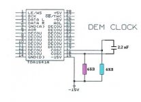
Are this schematic correct ?
Yes. But just leave the original 680pf in place. Dont over complicate first.
You can change later or if the resistors dont want to work with that size of the cap. I thing I used 120pf in my cd 40.
235.2 KHz, 350pF
256.58181 KHz, 318pF
282.24 KHz, 300pF
313.6 KHz, 260pF
352.8 KHz, 250pF
403.2 KHz, 203pF
470.4 KHz, 180pF
564.48 KHz, 145pF
705.6 KHz, 122pF
The capacitors need to have tight tolerance (1%).
So the C giving 176.4 kHz fDEM might be around 465 pF
For your picture soundhappy:
Perfect bypass would be with SMD size PPS caps, but looks nice and still could work.
Last edited:
Hi DanicoYes. But just leave the original 680pf in place. Dont over complicate first.
You can change later or if the resistors dont want to work with that size of the cap. I thing I used 120pf in my cd 40.
235.2 KHz, 350pF
256.58181 KHz, 318pF
282.24 KHz, 300pF
313.6 KHz, 260pF
352.8 KHz, 250pF
403.2 KHz, 203pF
470.4 KHz, 180pF
564.48 KHz, 145pF
705.6 KHz, 122pF
The capacitors need to have tight tolerance (1%).
So the C giving 176.4 kHz fDEM might be around 465 pF
For your picture soundhappy:
Perfect bypass would be with SMD size PPS caps, but looks nice and still could work.
I testet fews recordings today before and after i modified DEM clock and...
THANKS wow very impresed sound are much more " FULL " in all frequencies
and music flows with energy and keep all subtle nuances at the same time.
I just mached very closely resistors is easy to do, a keeper upgrade.
Do you changed two 100 uF BP Muse capacitors ?
I swap to 1 uF no-polarized...what was your choice ?
Thanks again and kind regards

Attachments

Glad you like the DEM mod. BP is not that bad on the output.
That time I did use Elna Cerafine or Silmic II.
In my Revox I use ClarityCap ESA, since its a very good sounding and not over priced.
But my secret cap is an old Siemens tantalum B45178 or any military version.
I got some for 10 cents/ piece then when I did run out of elna I started to use them.
They very clean sounding caps. It suprised me,too.
Glad you like the DEM mod. BP is not that bad on the output.
That time I did use Elna Cerafine or Silmic II.
In my Revox I use ClarityCap ESA, since its a very good sounding and not over priced.
But my secret cap is an old Siemens tantalum B45178 or any military version.
I got some for 10 cents/ piece then when I did run out of elna I started to use them.
They very clean sounding caps. It suprised me,too.
Ahoy Danico
Play few albums this evening i know well and with this modification is like completly " in new dimension " cd-player.
I was sceptic not beliver modern zillion bit's dac's are technicaly superior and outperform vintage Marantz
but not shure this old work incredible and is huge enjoyable

Think i keep op-amp stage and build tube output so i can switch between two options.
Any experience with teflon caps from Russia or Mundorf pio ?
Thanks thanks Danico !
Hope we have good news from MaccAu 😀
Greetings
- Status
- Not open for further replies.
- Home
- Source & Line
- Digital Source
- My first CD50 mod with NOS