Hello. i was thinking of building a preamp and trying biasing OPA2134 and NE5532 into class A,as described here Biasing Op-Amps into Class A . i
My concern is Has anyone done the same with these 2 opamps and with what results?where you satisfied with the results?
This is how i am going to apply it.I am also posting LT Spice simulation file and OPA2134,NE5532 spice models.I dont know if they are accurate enough.
My concern is Has anyone done the same with these 2 opamps and with what results?where you satisfied with the results?
This is how i am going to apply it.I am also posting LT Spice simulation file and OPA2134,NE5532 spice models.I dont know if they are accurate enough.
Attachments
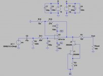
As-is, that's a pretty lightly-loaded circuit, and neither opamp type would break much of a sweat - not even a TL072 would, in fact. I'd be more worried about impedance imbalance (and noise) at this point, as R18/19 are a bit on the high side. I suggest you try something more like 5k6 and 3k, then noise ought to go down by 4-5 dB and there should also be more of a benefit to Class A biasing. (The exact magnitude partly depends on the effectiveness of available rail decoupling. Can't hurt to have the odd 10µ if that's a bit skimpy.)
Are you planning to use a volume pot in front of the whole shebang? That's always a compromise between worst-case output impedance (lower for lower values) and things like channel imbalance (usually better for higher values, for whatever reason). In case of an OPA2134 I'd stick with 10k-20k, NE5532 with its much lower input impedance distortion shouldn't have much of a problem with 50k or even 100k.
Preferably use bipolar (DIY version: two back-to-back) or low-leakage types for coupling caps.
Last edited:
That circuit uses some very odd values.
The resistance values are very high leading to avoidable noise.
The DC blocker goes to excessively low F-3dB.
& the RF filter goes to excessively high F-3dB.
Very odd.
Because they are specifying a FET input opamp there should be pretty low output offset.
But check it.
The resistance values are very high leading to avoidable noise.
The DC blocker goes to excessively low F-3dB.
& the RF filter goes to excessively high F-3dB.
Very odd.
Because they are specifying a FET input opamp there should be pretty low output offset.
But check it.
And put a DC blocker 100 - 220 uF bipolar cap after R1
Not a bad idea to change the value of R1 in 47R
Not a bad idea to change the value of R1 in 47R
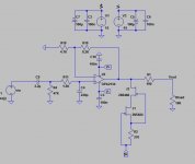
Thank you for your answers.So something like this would be better...
No volume pot for the time being,maybe i use one (10K or 22K) in the future.I reduced R18-R19 values a bit as you suggested.
The 47uF at input was a typo mistake.4.7uF I meant to say.I reduced the bandwith now.I dont think a dc blocking capacitor after R1 is needed because there wont be any significant offset. maybe 7mv at most? next stage input (power amplifier)already has a dc blocking cap.
Attachments
then you do not want an extra DC blocking cap at the output of the Source............ next stage input (power amplifier)already has a dc blocking cap.
This is where dual output sockets would be very handy. One stereo set with AC coupled output and the other stereo set with DC coupled output.
And repeat the duplication at the input to the power amp.
Leaves the operator/user with the option to bypass the inferior/inadequate capacitor.
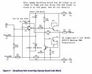
The Hifisonix Ovation Symphony preamplifier, designed by diyAudio member bonsai, takes it one step further. It biases the opamp in Class A (via resistor R2) AND it adds a high current output buffer which also operates Class A. The output buffer is an emitter follower (U2top) with a constant current source load (U2bot + Q1). The current is equal to VBE1/R3 and is about 50mA as shown.
Link to Hifisonix site
_
Link to Hifisonix site
_
Attachments
Thank you for your answers.So something like this would be better...
No volume pot for the time being,maybe i use one (10K or 22K) in the future.I reduced R18-R19 values a bit as you suggested.
The 47uF at input was a typo mistake.4.7uF I meant to say.I reduced the bandwith now.I dont think a dc blocking capacitor after R1 is needed because there wont be any significant offset. maybe 7mv at most? next stage input (power amplifier)already has a dc blocking cap.
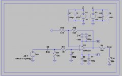
The combination of a non-inverting configuration, low gain, and a 1.5k resistor in series with the non-inverting input will produce distortion at high frequency on the JFET-input op amps that you're considering. One solution, if you must keep the 1.5k resistor on the non-inverting input is to choose feedback resistor values such that their equivalent impedance as seen by the inverting input (their parallel combination) is equal to 1.5k. That way the equivalent source impedance at each of the op amp inputs is matched.
The combination of a non-inverting configuration, low gain, and a 1.5k resistor in series with the non-inverting input will produce distortion at high frequency on the JFET-input op amps that you're considering. One solution, if you must keep the 1.5k resistor on the non-inverting input is to choose feedback resistor values such that their equivalent impedance as seen by the inverting input (their parallel combination) is equal to 1.5k. That way the equivalent source impedance at each of the op amp inputs is matched.
all resistor values can be changed,i am not to keep any value. so you suggest that R11 resistor value should equal to the parallel combination of R18 and R19? In our case R18//R19 = 3K?
Attachments
Last edited:
all resistor values can be changed,i am not to keep any value. so you suggest that R11 resistor value should equal to the parallel combination of R18 and R19? In our case R18//R19 = 3K?
Yes. However, I would not increase R11 as this will add additional noise . Rather I would decrease R18 and R19.
1k6 & 2k7 give ~1k when paralleled. Gain stays @ 2.7times (+8.6dB)
1k & 470pF gives the same RC
I forgot about the increase in distortion when a jFET input sees unbalanced source impedances. I think D.Self mentions this.
1k & 470pF gives the same RC
I forgot about the increase in distortion when a jFET input sees unbalanced source impedances. I think D.Self mentions this.
1k6 & 2k7 give ~1k when paralleled. Gain stays @ 2.7times (+8.6dB)
1k & 470pF gives the same RC
I forgot about the increase in distortion when a jFET input sees unbalanced source impedances. I think D.Self mentions this.
He shows the effects in both his book on Small-Signal Audio Design and his book on active crossovers (great references). I dove a bit into the on-chip mechanisms in JFET-input op amps in an article last year:
http://www.ti.com/lit/an/slyt595/slyt595.pdf

- Status
- Not open for further replies.
- Home
- Source & Line
- Analog Line Level
- NE5532,OPA2134 Class A biased.Worth to try?Your experience?