so after many new lspcad calculations and test + measuring using minidsp i think that the new filters are little better than the previous. What do you think about those graphs?
i actually changed the cross frequencies. All filters are LR4 and they are 3-4 peak/noth filters on each speaker. Woofer also have a baffle step correction circuit and the tweeter one all pass filter for phase correction.
The cross frequencies are 350 and 2kz. The acoustics are little different. Using the 2khz cross on the midrange there is no the 2,7k peak 3rd harmonic anymore which i had with 3khz cross. I listened the speaker for a while and maybe i must lower the mids and highs about 0.5db.
So what do you think?
(the 2x4 minidsp makes different audible noises so i would not suggest to use it as cross for high quality speakers but for developing a active cross is just fine).
Attachments

Last edited:
It all looks really good except for the bass. The step response between midrange and woofer isn't as smooth as it could be, and the bass is rippling up and down quite a bit. Did you add a lot of EQ sections to it?
Also, chart the mid and bass drivers with phase plots please. Exclude tweeter. I'd like to see how that's matching up.
Here's the target curve I designed my last speakers to, and I'm very happy with it in room. This will make it easier for you toe valuate what I'm talking about, and see if it works for you.
Best,
Erik
Last edited:
hi,
the woofer section has the 4th order LR filter, a low shelf filter and 2 notch filters. I will try to do it with 1 notch less. The rippling bass i thing is due to room resonances. The speaker is measured on the floor and the woofer is about 70cm above the floor. I will try to extend the bass lift to about 400-500z and listen a few songs and let you know.
thank you for helping me. 🙂
hello Eriksquires
today i tried your target curve and 1 another similar to yours (the descent was extended to about 2k)
those curves are better they don't sound too much bright as the flat curve. They are much closer to the natural voices.
I will keep those responses and will design an analog crossover now. I played a little bit with the delays in minidsp and the step response cannot be better. If i try to add delay to the mid unit the notch is not as deep at the cross frequency. (the baffle is not flat the mid is already behind the woofer as the tweeter is behind the midrange). the deepest noch at the high cross frequency is when i add a delay to the tweeter (60us).
so what is your opinion on those measurements?
the cross has the following filters:
woofer section: 24db LR4 at 350hz, low shelf, 2 notch
mid section: 24db LR4 at 350 and 24db LR4 at 2k, 3 notch
tweeter section: 24db RL4 at 2k, 3 notch and an 1st order allpass for the delay
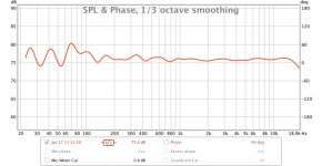
i am uploading the mid-woofer plots you wanted to see with 1/3 smoothing and gating
today i tried your target curve and 1 another similar to yours (the descent was extended to about 2k)
those curves are better they don't sound too much bright as the flat curve. They are much closer to the natural voices.
I will keep those responses and will design an analog crossover now. I played a little bit with the delays in minidsp and the step response cannot be better. If i try to add delay to the mid unit the notch is not as deep at the cross frequency. (the baffle is not flat the mid is already behind the woofer as the tweeter is behind the midrange). the deepest noch at the high cross frequency is when i add a delay to the tweeter (60us).
so what is your opinion on those measurements?
the cross has the following filters:
woofer section: 24db LR4 at 350hz, low shelf, 2 notch
mid section: 24db LR4 at 350 and 24db LR4 at 2k, 3 notch
tweeter section: 24db RL4 at 2k, 3 notch and an 1st order allpass for the delay
i am uploading the mid-woofer plots you wanted to see with 1/3 smoothing and gating
Attachments


hello,
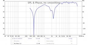
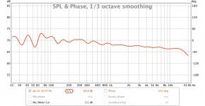
finally after i tried your target curve and the Bruel&Kjaer curve i probably choose the second one. On the picture you can see my final curve an response with mid inverted. I played a lot with the minds delays so i can have a better step response. I cannot have better step whatever i do with the delays. I had a very good step (one peak and slow step down) only when i try to use a 6db/oct filters. Those magnesium speakers don't like 6db/oct filters. Using the RL4 i cannot get better step response.
finally after i tried your target curve and the Bruel&Kjaer curve i probably choose the second one. On the picture you can see my final curve an response with mid inverted. I played a lot with the minds delays so i can have a better step response. I cannot have better step whatever i do with the delays. I had a very good step (one peak and slow step down) only when i try to use a 6db/oct filters. Those magnesium speakers don't like 6db/oct filters. Using the RL4 i cannot get better step response.
Attachments
You know I want you to use what you like. 🙂 For me that B&K curve would be a little dry. What I wanted to see and it's too complicated was just how well the drivers are matching up to each other in phase. Not just at the exact middle. The driver's phase angles need to dance together through the crossover section. Much like dancing when you pull your partner towards you, you meet, and then you go your separate ways.
May I ask why 4th order slopes?
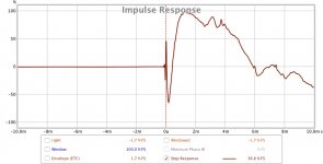
Also, I'm confused. The step response says there's no delay at all. If this is all in DSP I think you needed to delay the tweeter and midrange even more! 🙂 You should be able to have 1 rising line together, not three. You can be much more agressive in your time delays in DSP world.
Also, could you send a picture of your front baffle? I'm still not sure what you are trying to make. If each driver is in a separate enclosure, and you can move them, then you should be able to keep your DSP to 0 delays, and move the drivers until you get a perfect step response, or at least much closer. Then you'll need to completely redo your crossover..... 🙂
Best,
Erik
May I ask why 4th order slopes?
Also, I'm confused. The step response says there's no delay at all. If this is all in DSP I think you needed to delay the tweeter and midrange even more! 🙂 You should be able to have 1 rising line together, not three. You can be much more agressive in your time delays in DSP world.
Also, could you send a picture of your front baffle? I'm still not sure what you are trying to make. If each driver is in a separate enclosure, and you can move them, then you should be able to keep your DSP to 0 delays, and move the drivers until you get a perfect step response, or at least much closer. Then you'll need to completely redo your crossover..... 🙂
Best,
Erik
hello,
the drivers at the baffle are properly aligned. When i don't use any filter or delays at all then the step is almost ideal. One rise and slow step down. All drivers and all notes at the same time. When i use only filters 6db/oct then the result is also very good almost like without any filters.
Also, at the beginning, in lspcad when i insert the measured without any filters curves and when i give the exact Y,Z of the drivers then the measured total-calculated curves matches totally.(using Z=0 on all drivers) The problem begins when i use those 24db filters and notch filters. Then , because those filters and notches add a frequent variable phase shifts, it cannot be completely aligned using delay. The different phase shifts at different frequencies does not allow the speakers to play simultaneously the same notes. The only thing i can achieve using a 40uS delay on the tweeter is the dip at the cross frequency when inverted. the dip at the low cross is without any delay.
So practically what can be done about it? i tried to use 12db filters also but without any much improvement. The 6db are perfect but there must be many notch filters and i don't know if the tweeter can handle it. I don't want to rise the cross frequency because of the midrange distortion at 2.7K. Those drivers have many peaks (magnesium)
Attachments
Last edited:
what i did not try is to use for example 2nd filter on woofer, 3rd on HP midrange, 2nd on LP midrange and 3rd on tweeter.
do you thing it could help?
do you thing it could help?
what i did not try is to use for example 2nd filter on woofer, 3rd on HP midrange, 2nd on LP midrange and 3rd on tweeter.
do you thing it could help?
Well, I think you are using a big hammer. 🙂
Remember that the point is that the driver + crossover adds up to a certain filter. That is, 2nd order low pass naturaly in a driver + 1st order crossover = 3rd order.
In my own designs, few as they are, I've never been able to really do 4th and 4th. I may do 2nd and 2nd, or 1st and 3rd order, and even then it's never exactly 1st or 2nd or 3rd due to the complicated interactions.
Your notch filters shouldn't be having that big of an effect. I suspect you are doing them first? Do it the other way. Focus on good transitioning from driver to driver, then only fix what shows up in the combined FR.
You don' thave to have perfect time alignment to sound good. Your transition from driver to driver in the first couple of step responses was mostly pretty good except in the bass. However, if you are going to get that complicated, i'd stay digital and then add all the time delay I wanted. 🙂
Best,
Erik
Last edited:
hello Erik,
today i tried different slopes and filters again in lspcad. i can get better step response using only LR 2nd order filters. When i say better response i mean that in simulation there is one step peak one down and slowly rise again. Can you please do some simulation using my curves and tell me your opinion what is the best to use?
today i tried different slopes and filters again in lspcad. i can get better step response using only LR 2nd order filters. When i say better response i mean that in simulation there is one step peak one down and slowly rise again. Can you please do some simulation using my curves and tell me your opinion what is the best to use?
Attachments
hello Erik,
today i tried different slopes and filters again in lspcad. i can get better step response using only LR 2nd order filters. When i say better response i mean that in simulation there is one step peak one down and slowly rise again. Can you please do some simulation using my curves and tell me your opinion what is the best to use?
That sounds good! 🙂 If you can use 2nd order filters, why not? 🙂 More important is the merging of one to the other. The only time this may be a negative (lower order slopes) is when trying to push a tweeter to a very low crossover point. For instance, it may be fine at 2kHz with 12db/octave, but if you needed to go to 1,600Hz you might need 24db/octave to prevent damage.
have you listened to them?
Erik
I should point out, even very experienced designers have trouble with passive 4th way filters. They are easy in active, using ideal resistors and flat impedances but when you throw in the speaker EQ work, they become just as difficult.
hello Erik,
no i have not listened them. Tomorrow i will set up the minidsp and will do a fine tuning to the filter according real measurements as i do until now. Every time i calculate the cross using lspcad and then input the results into minidsp i must make some fine tuning (very small changes) to the minidsp according to real measurements so i can have those good responces. I will make analog active crossover not passive. Making 24db with 7-8 notch in passive version will be very costly and large. This is active system. Now i am using another cross whitch i had designed about a year ago. But because i am not really happy with the result i am designing another one now. Then i had only the lspcad and i was not able to measure anything. I used the manafacturer responces whitch are quite different in my enclosures.
I will post tommorow the results using only 12db filters.
hello
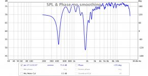
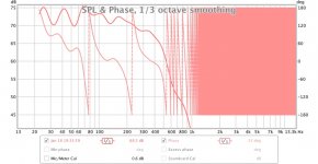
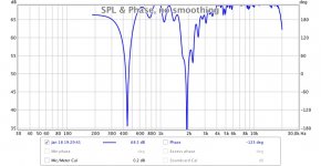
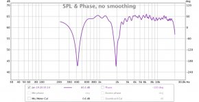
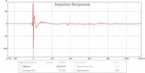
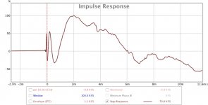
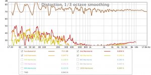
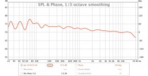
today i tried 2nd order different types off filters. Finally i like the 2nd order L-R filter on all section. below you can see the differences between all 2nd and all 4th order L-R filters. The target curves are B&K as i have chosen previously. (more warm and closer to real sound).
So what do you think? is the 2nd order better than 4th? I think that yes it is.
At the midrange inverted plot the tweeter null will be better. The dsp don't allow to input 70us but 60us or 80us. with the analog version it will be exactly as needed.(using multi turn trimmer)
Attachments
-
 4th order L-R inverted.jpg84.8 KB · Views: 59
 -
 impulse 4rd order L-R.jpg61 KB · Views: 59
 -
 step 4th order L-R.jpg62.2 KB · Views: 59
 -
 distortion 4th order R-L.jpg113.2 KB · Views: 59
 -
 4th L-R B&K.jpg83.5 KB · Views: 48
 -
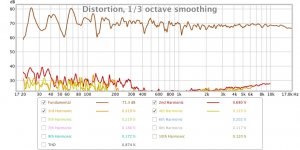 distortion 2nd order L-R.jpg107.3 KB · Views: 113
 -
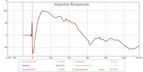 step 2nd order L-R.jpg66.1 KB · Views: 125
 -
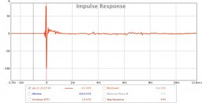 impulse 2nd.jpg67.1 KB · Views: 129
 -
 2nd order L-R inverted.jpg78 KB · Views: 130
 -
 2nd L-R B&K.jpg83.2 KB · Views: 129
Last edited:
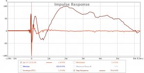
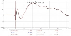
That's looking good. 🙂 Take a look at the woofer and midrange FR + PHase plots. I think you'll see the driver alignmetns are dancing together longer, a good thing. There's a tiny notch in the step response between the midrange and woofer, but everything else looks pretty good. Now, the killer. Take a look at your impedance plots... 🙂
Best,
Erik
Best,
Erik
Looks good! Enjoy....
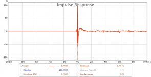
Of course, those graphs #4 in both rows are your Step, not Impulse response.
Of course, those graphs #4 in both rows are your Step, not Impulse response.
hi,
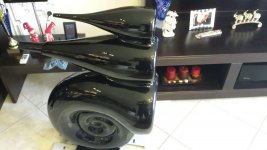
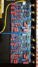
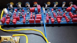
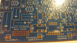
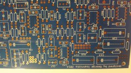
i want to inform you that after many many simulation using lspcad and Leap together with the mindsp 2x4 (which helped a lot) i finally designed the final filters. With the help of the Eagle cad software i designed the pcbs board need for the crossover. Then , for the first time (i always made the pcbs by myself), i send the files to a pcbs manufacturer the pcbway.com. the boards arrive about after 1 month to Greece but i am impressed with the board quality and prices. The board is 10x15cm and i chooses a blue finish with nickel-gold on cooper. The silkscreen has good quality and it well is centered. The price was so low that it is not worth to make this boards at home anymore. On the photos you can see those boards and the ready crossover. I already have ordered another boards for my new headphone amplifier from them. (5 pcs 2 sided 100x100mm for 13$)
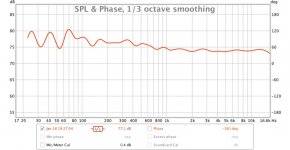
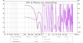
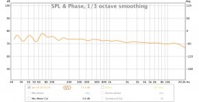
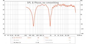
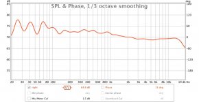
The final measurements of the analog crossover was very close to the minidsp and there is no need to make any adjustment to the analog crossover. Only set the each section level and the tweeter phase. (for the level-phase i have a multi turn resistors) I found the sound much better with this 2nd order cross in companion with the 4rd order. I always thought that choosing a stepper order will make things better but i now see that it is not always true. If one design a proper 2nd order crossover, choosing the proper cross frequencies and take care of those speakers resonances, it can sound very good. On the photos you can see my final response measured at tweeter level and 1m distance from it.
I must say that the mindsp is very good tool for crossover developing but there is a BIG difference in sound with the analog one with the same responses-phase. The analog one has much much clearer and detailed sound, lower noise and distortion. Of course the mindsp is much much cheaper compared to the analog one if it is using good quality components.
Eriksquires 🙂 As the impedance plots, i don't care. it was enough complicated already. 🙂. (of course in active crossover design there is no impedance plots)
i want to inform you that after many many simulation using lspcad and Leap together with the mindsp 2x4 (which helped a lot) i finally designed the final filters. With the help of the Eagle cad software i designed the pcbs board need for the crossover. Then , for the first time (i always made the pcbs by myself), i send the files to a pcbs manufacturer the pcbway.com. the boards arrive about after 1 month to Greece but i am impressed with the board quality and prices. The board is 10x15cm and i chooses a blue finish with nickel-gold on cooper. The silkscreen has good quality and it well is centered. The price was so low that it is not worth to make this boards at home anymore. On the photos you can see those boards and the ready crossover. I already have ordered another boards for my new headphone amplifier from them. (5 pcs 2 sided 100x100mm for 13$)
The final measurements of the analog crossover was very close to the minidsp and there is no need to make any adjustment to the analog crossover. Only set the each section level and the tweeter phase. (for the level-phase i have a multi turn resistors) I found the sound much better with this 2nd order cross in companion with the 4rd order. I always thought that choosing a stepper order will make things better but i now see that it is not always true. If one design a proper 2nd order crossover, choosing the proper cross frequencies and take care of those speakers resonances, it can sound very good. On the photos you can see my final response measured at tweeter level and 1m distance from it.
I must say that the mindsp is very good tool for crossover developing but there is a BIG difference in sound with the analog one with the same responses-phase. The analog one has much much clearer and detailed sound, lower noise and distortion. Of course the mindsp is much much cheaper compared to the analog one if it is using good quality components.
Eriksquires 🙂 As the impedance plots, i don't care. it was enough complicated already. 🙂. (of course in active crossover design there is no impedance plots)
Attachments
-
 step.jpg65.8 KB · Views: 46
 -
 impulse.jpg61.5 KB · Views: 56
 -
 final.jpg80.4 KB · Views: 53
 -
 20160316_165110_resized.jpg465.4 KB · Views: 73
 -
 20160313_130907_resized.jpg544 KB · Views: 67
 -
 20160313_130921_resized.jpg378.5 KB · Views: 61
 -
 20160316_165101_resized.jpg848 KB · Views: 66
 -
 20160316_165154_resized.jpg924.5 KB · Views: 66
 -
 final rev.jpg84.5 KB · Views: 54

I may have been drunk or off my normal anti-psychotic medications when I asked for impedance plots. 🙂
Nice looking boards! I like your use of connectors too.
How do you find the sound quality in analog vs. miniDSP? The major reason that I am sometimes tempted to do an all digital crossover is the time delay. It would be interesting to compare time aligned with merely phase aligned speakers directly, which I've never been able to.
- Status
- Not open for further replies.
- Home
- Loudspeakers
- Multi-Way
- active 3way crossover phase