It seems natural to me, that a faster amplifier has a higher bandwidth?
Yes. And?
I don't think that is true. Black was well aware that amps are nonlinear in your sense that they create harmonic frequencies and that fb improves that. The requirement for fb is that the amp is a linear system meaning it is time-invariant.
Baxandall and Putzeys used a pathological example to exaggerate the difference between Black's approximation and a more complete, but very difficult (partial differentials) solution. If Black were exact, distortion in the Baxandall and Putzeys example would fall monotonically, a simple algebraic solution.
I'll get into trouble saying it this way, but here goes: Black's model allows for distortion "the first pass" through the amplifier but not "the second pass, with feedback". This is not how feedback works, at all, but I believe it explains the Black model.
Much thanks, as always,
Chris
Does the amplifier go through more than one cycle of feedback..??.. surely when you have square wave overshoot bordering to stability problems the amplifier must keep correcting itself while it attains balance, otherwise I would consider the system so stiff that is does not overshoot its target. So in principle all distortions through the first run and then corrected with the excess gain (down to distortions figures) the next.
No! No! No!
This is the feedback delay myth all over again, but wearing different trousers.
The feedback at any time contains a reaction to the current instantaneous input value plus the history of all input values since the amplifier was switched on. This is simply the action of a filter in the forward path.
Only if an amplifier has significant hysteresis or a dead spot in the middle do you get it overshooting and correcting itself.
Baxandall and Putzeys used a pathological example to exaggerate the difference between Black's approximation and a more complete, but very difficult (partial differentials) solution. If Black were exact, distortion in the Baxandall and Putzeys example would fall monotonically
Chris
correct but not partial DEq , rather, non-linear. Black's and all other ideas presented so far are linear models. Linear doesn't refer to the transfer function. Only ideal transformers show a linear transfer function.
Only if an amplifier has significant hysteresis or a dead spot in the middle do you get it overshooting and correcting itself.
... because it is no longer time-invariant.
Jan
Yes. And?
I did not get the quote right in my last post...Amplifier delay does not depend on feedback. It depends on the amplifier bandwidth.
An amplifier with 100kHz bandwidth and feedback has the same delay as a second amplifier without feedback and with the same 100kHz bandwidth.
Amplifiers delay is rather meaningless anyway.
Any audio amplifier has > 20kHz bandwidth and
therefore the delay is < 50 us.
Important is the GROUP DELAY. This tells you if the amplifier has a good pulse response.

@Jan:
I was referring to my first post above which is an answer to the original question of Sérgio in this thread.
I basically said that it is not possible to distinguish from the outside if an amplifier has feedback or not.
What do you think is wrong with this statement?
No! No! No!
This is the feedback delay myth all over again, but wearing different trousers.
The feedback at any time contains a reaction to the current instantaneous input value plus the history of all input values since the amplifier was switched on. This is simply the action of a filter in the forward path.
Only if an amplifier has significant hysteresis or a dead spot in the middle do you get it overshooting and correcting itself.
I know this is all happening in time, or so close in time that time does not matter, yet the mechanism must be critically damped or we get tendency to overshoot and thus have oscillation, as we see on squares when the amplifier is not compensated sufficiently.
What I am chasing here the the condition for the differential FB to do its job. getting rid of excess gain and set the output level to the set ration.
In other FB. applications like speed control where there's work that involves mass there's often difficulty in stopping acceleration to the desired speed. thus you'll see a ripple on the speed curve. just like you see it on the top of a square. the feedback regulated force must be critically damped to reach stability in rotation.
Reading my own post, I realize it's all bogus.. The condition is that the OLG has sufficient phase margin. Sorry...
Last edited:
The condition is that the OLG has sufficient phase margin. Sorry...
Indeed! I cut my feedback teeth on slewing air defense guns. EXACTLY the same issues: you want to slew as fast as possible but not overshoot the position you are going to and certainly not (damped) oscillations. In this instance a real matter of life and death!!
Jan
I basically said that it is not possible to distinguish from the outside if an amplifier has feedback or not.
What do you think is wrong with this statement?
I think you are right. I don't know of any test on a black box that tells you if an amp inside has feedback or not.
The question is: can I design an amp, open loop, with the same transfer function as a feedback amp? I think you can, so it cannot be tested black box.
Jan
You need to read up on feedback/servo theory. To do this you need to understand complex numbers/functions etc. Anything less may lead you astray, as some of the results of the correct theory (like many correct theories) are counter-intuitive.MiiB said:What I am chasing here the the condition for the differential FB to do its job. getting rid of excess gain and set the output level to the set ration.
Just out of curiosity: as it seems to me for the human brain these abstract/complex
phenomenas are often quite hard to imagine, understand properly and therefore to
discuss especially in writing.
Couldn't we use concrete proofs each and every time to show the reality if we are right at all?
I understand that this looks uneffective at 1st sight but looking back topics discussing such things
shows me that this process needs a lot more time/energy to convince eachother via just written explanations.
Either real world measurements or at least simulations would be the format (the fewer words the better... 🙂).
But untill then all other stuff can be just (false) belief/opinion even for ourselfs.
I am sure you all are familiar with the "Proof of Concept" methodology.
With (at least) simulations we could use this to prove/explain each little thing in "reality".
Or it's nonsense..? 😉
You need to read up on feedback/servo theory. To do this you need to understand complex numbers/functions etc. Anything less may lead you astray, as some of the results of the correct theory (like many correct theories) are counter-intuitive.
Been there done that, I do have an engineering degree, with math you need to idealize the mechanisms in order to fit them into the equations, what I try to grasp is the physical understanding of the math, as to get a feel for the influence of the device parameters. This is an essential part of developing strong concepts. It's good that you can calculate something others have created. To shift that into a multifaceted picture and deeper understanding is for me a necessity for beeing creative. That is how I get the needed fundamentals to design anything.
Does the amplifier go through more than one cycle of feedback..??..
Like this?
https://en.wikipedia.org/wiki/Video_feedback
And the relevance of that is..??
Why do you take my question to the previous post out of context.. ???
Why do you take my question to the previous post out of context.. ???
Feedback theory is one of those things where 'physical understanding' can lead you astray. I have no intuitive feel for why increasing loop gain can, under the right circumstances, make an unstable loop stable again. (conditional stability) A Bode plot shows this, though, and that satisfies me. Maybe that is because I am a physicist?MiiB said:Been there done that, I do have an engineering degree, with math you need to idealize the mechanisms in order to fit them into the equations, what I try to grasp is the physical understanding of the math, as to get a feel for the influence of the device parameters.
And the relevance of that is..??
Why do you take my question to the previous post out of context.. ???
Because it reminded me of this very handy device called a PCB trace.
Attachments
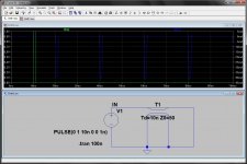
you really should quit abusing the parts, models, sim conditions
a un-terminated transmission line is a infinite Q resonator - and not much use describing actual circuits with finite. lossy Z driving practical wires with loss, and connected at the other end to other parts with finite, lossy input Z
a un-terminated transmission line is a infinite Q resonator - and not much use describing actual circuits with finite. lossy Z driving practical wires with loss, and connected at the other end to other parts with finite, lossy input Z
you really should quit abusing the parts, models, sim conditions
a un-terminated transmission line is a infinite Q resonator - and not much use describing actual circuits with finite. lossy Z driving practical wires with loss, and connected at the other end to other parts with finite, lossy input Z
I usually don't do that, however since some people here insist every 3rd post that amps are ideal or at least linear, interactions are instantaneous, time delays don't exist etc. I decided I could indulge in this type of fun too.

any complex conversation can be derailed by such practice - maybe you should consider helping in the larger picture rather than intentionally being unhelpful, being deliberately annoying
if you can't put a reasonable construction some wording in a "conversational" forum post just ask the honest question about the assumption(s) you think are missing or incorrect instead of doing the lifting a "sound bite", denying context, exaggerating and ridiculing "black bag" rhetorical thing
to me you are sounding bad sense "Sophomoric" in these feedback threads - there are reasons Linear Systems theory is taught, still used for linear audio amplifier design for 70+ years now
if Linear Systems Theory didn't "work", have a useful range of applicability, you would think over several professional lifetimes Industry would have forced Academia, Uni EE programs to drop it if it hadn't proven a valuable EE design tool
Last edited:
- Status
- Not open for further replies.
- Home
- Amplifiers
- Solid State
- Feedback loop speed