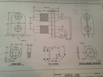
Man, their engineering drawings leave a lot to be desired. Anyone have enough measurements to make a decent PCB footprint?
http://www.cardas.com/images/grfa_prt_drawing.jpg
http://www.cardas.com/images/grfa_prt_drawing.jpg
Man, their engineering drawings leave a lot to be desired. Anyone have enough measurements to make a decent PCB footprint?
http://www.cardas.com/images/grfa_prt_drawing.jpg
This problem has been with us forever. Just scale the dimensions you need off of their drawing.
This problem has been with us forever. Just scale the dimensions you need off of their drawing.
Drawing should not used to scale from these days, there is no scale on the drawing and it clearly states it is not an eng9ineering drawing. The pertinent dimensions should be on there, in this instance they are not, which if it is a Cardas part they should be privy to a proper drawing. This is one of the worst I have ever seen, usually the correct dimensions can be extracted from the drawing, in this case nope...
Man, their engineering drawings leave a lot to be desired. Anyone have enough measurements to make a decent PCB footprint?
http://www.cardas.com/images/grfa_prt_drawing.jpg
Time to buy one and a nice set of calipers.
")
The good news is that printers are much better today than the old days. You can probably achieve very good 1 to 1 printing results, so you should be able to print a silkscreen or PCB layout and compare to a real part after design.
Best,
Erik
Always print a 100mm scale on your prints in a corner, get a calibrated metal ruler (or a loupe with grads if you really need the accuracy) then you can fine check your prints for scaling factors, also having a full sheet Cartesian co-ordinates print to check the whole sheet is a good idea. Use to do this in t'old days when we use to plot or print artworks for simple boards and instrument panels...
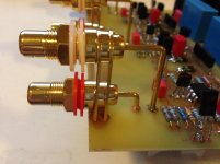
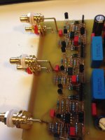
Yeah, that looks perfect. If I wanted to keep the ground isolated from the case using the shoulder washers on both sides, it might be easier to only mount the right most pair of ground connectors on the PCB and put the edge of the board "between"? This might put less stress on things too.
- Status
- This old topic is closed. If you want to reopen this topic, contact a moderator using the "Report Post" button.
- Home
- Design & Build
- Parts
- Measurements for Cardas GRFA PRT