Hello,
My first post here. Seriously amazing content in this forum!
I am new to circuit design and am trying to breadboard up the attached tape head preamp circuit using a stereo cassette tape head. I have etched it as well from the existing pcb design which worked well with a 9v battery. Ultimately I am looking to raise the gain of this circuit a bit and stop the feedback and noise.
Here is my issue: I'm attempting to use a regulated 9v 650mA power supply in place of the battery. Both in using the pcb and the breadboarded version the circuit will go into oscillation/feedback (again zero feedback with a 9v battery). When I use 10k pots on the L/R outputs to attenuate the volume and turn them down a touch the feedback stops, very strange. When I use pots to attenuate R1 and R7 the feedback stops as well along with volume dropping of course. Changing R1/R7 is what is suggested in the data sheet for the LA3161 to increase gain. Is this what is called a ground loop? Sounds like a an insanely loud synth basically.
I've also been attempting to boost the gain of this circuit as well as keep the EQ fairly intact. I have tried replacing R4/R6 with a 100k pots, similar results as above. I have attempted replacing R1/R7 with pots as well but when you get down below 50ohms then the feedback starts again. I hope this is fairly clear.
Best,
E
Attachments
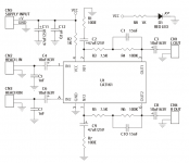
One thing looks a bit odd (unless its a typo). R2 @ 1k. That's very high for a series feed resistor, something closer to 10 ohms would be more normal. Also there would normally be decoupling on that Vcc pin such as your C11 and C12.
And welcome to diyAudio 🙂
And welcome to diyAudio 🙂
1) add a 47 to 220uF cap from pin 4 to ground
2) you can't "add more gain" , that IC is already run at maximum possible, and is well matched to what a tape head delivers, if anything add a stereo level pot at its output and then go into an extra gain stage, 5X to 10X is fine.
The stereo volume pot must be Audio/Log taper and from 10k to 50k value; 22/25k a nice middle value.
3) what are you trying to drive with this preamp?
4) you currently have grounding/shielding problems.
One thing looks a bit odd (unless its a typo). R2 @ 1k. That's very high for a series feed resistor, something closer to 10 ohms would be more normal. Also there would normally be decoupling on that Vcc pin such as your C11 and C12.
And welcome to diyAudio 🙂
Thanks Mooly 🙂
In what ways does changing the 1k feed to a 10ohm alter things? Again I'm verrry beginner.
Also, How would I do decoupling from the Vcc pin and what values would be a good start?
Last edited:
1) add a 47 to 220uF cap from pin 4 to ground
Great thanks will try this.
2) you can't "add more gain" , that IC is already run at maximum possible, and is well matched to what a tape head delivers, if anything add a stereo level pot at its output and then go into an extra gain stage, 5X to 10X is fine.The stereo volume pot must be Audio/Log taper and from 10k to 50k value; 22/25k a nice middle value.
On the IC data sheet (which shows a similar circuit) it states it can be increased. But I'm guessing you are saying that from what you see with this updated circuit it's already maxed out? Do you happen to know of a simple stereo gain stage you could point me to that would give me 5x-10x? I'm looking for something fairly minimalist (few parts). On my particular project I have to make it one pot for each channel. So far 10k has been perfect and was suggested by the designer of this circuit. Though I haven't been able to get any more info from them.
3) what are you trying to drive with this preamp?
Just a stereo cassette tape head. Then from the preamp right into the line inputs in a mixer. It just needs a bit more gain as well as trying to get noise down somehow.
4) you currently have grounding/shielding problems.
Also, is there a smaller gauge shielded cable that everyone uses? I have had a hard time finding something that is flexible (which I would love due to case size restraints). Is shielded cable needed between both the head and pcb as well as the pcb to 1/4" outputs?
This is all being mounted inside of a small aluminum enclosure. I also have my little power jack panel mounted as well. But it's a plastic jack which means it's floating from the enclosure maybe? Would a metal power jack help with any grounding issues? The stereo cassette head is also mounted directly to to the aluminum enclosure as well (it's an experimental sound device). I know this is a lot of information. Thanks so much for your help!
I suspect you are using regular microphone shielded cable, or guitar type one.Also, is there a smaller gauge shielded cable that everyone uses? I have had a hard time finding something that is flexible (which I would love due to case size restraints). Is shielded cable needed between both the head and pcb as well as the pcb to 1/4" outputs?

Although electrically fine,they are meant to lie on the floor, stepped on and in general abused, so they are quite thick and hard , think 9 to 10mm thick, about a regular drawing pencil, similar to TV cable.
For internal chassis wiring, a much thinner type exists, think less than half as thick as the others, some 4mm, which is quite flexible.
It also often comes with spiral twisted around shielding, much easier to peel out and twist for soldering than criscrossed "net type" shields.
An externally hosted image should be here but it was not working when we last tested it.
I suspect you are using regular microphone shielded cable, or guitar type one.
Although electrically fine,they are meant to lie on the floor, stepped on and in general abused, so they are quite thick and hard , think 9 to 10mm thick, about a regular drawing pencil, similar to TV cable.
For internal chassis wiring, a much thinner type exists, think less than half as thick as the others, some 4mm, which is quite flexible.
It also often comes with spiral twisted around shielding, much easier to peel out and twist for soldering than criscrossed "net type" shields.
An externally hosted image should be here but it was not working when we last tested it.
Cool thanks, Yea I'm actually using this grey shielded cable that has two wires inside. I may have to keep with it to have things organized just as long as the Left and Right audio signals don't need to be separated/shielded from each other?
Also, I messed up the formatting in my last response to you so I had more questions and answers in the "Quote" box.
1) add a 47 to 220uF cap from pin 4 to ground
Great thanks will try this.
2) you can't "add more gain" , that IC is already run at maximum possible, and is well matched to what a tape head delivers, if anything add a stereo level pot at its output and then go into an extra gain stage, 5X to 10X is fine.The stereo volume pot must be Audio/Log taper and from 10k to 50k value; 22/25k a nice middle value.
On the IC data sheet (which shows a similar circuit) it states it can be increased. But I'm guessing you are saying that from what you see with this updated circuit it's already maxed out? Do you happen to know of a simple stereo gain stage you could point me to that would give me 5x-10x? I'm looking for something fairly minimalist (few parts). On my particular project I have to make it one pot for each channel. So far 10k has been perfect and was suggested by the designer of this circuit. Though I haven't been able to get any more info from them.
3) what are you trying to drive with this preamp?
Just a stereo cassette tape head. Then from the preamp right into the line inputs in a mixer. It just needs a bit more gain as well as trying to get noise down somehow.
4) you currently have grounding/shielding problems.
Thanks Mooly 🙂
In what ways does changing the 1k feed to a 10ohm alter things? Again I'm verrry beginner.
Also, How would I do decoupling from the Vcc pin and what values would be a good start?
I'm sorry, I must have missed your earlier replies.
The 1k feed resistor seems high because the resistor will drop a voltage in proportion to the current drawn by the chip. Now I don't know what the current draw is for that IC but it could typically in the 2 to 10 ma region which would meant the resistor is dropping 2 to 10 volts and not only that, the 1k on its own means that the power pin of the chip is at high impedance (hence the need for the cap at this point).
Do you happen to know of a simple stereo gain stage you could point me to that would give me 5x-10x? I'm looking for something fairly minimalist (few parts).
An opamp such as TL072 or NE5532 and a few resistors are all that are needed to make a near perfect gain stage.
If you need a worked example then just ask 🙂
I suspect you are using regular microphone shielded cable, or guitar type one.
Although electrically fine,they are meant to lie on the floor, stepped on and in general abused, so they are quite thick and hard , think 9 to 10mm thick, about a regular drawing pencil, similar to TV cable.
For internal chassis wiring, a much thinner type exists, think less than half as thick as the others, some 4mm, which is quite flexible.
It also often comes with spiral twisted around shielding, much easier to peel out and twist for soldering than criscrossed "net type" shields.
An externally hosted image should be here but it was not working when we last tested it.
This preamp has a high shelf hiss or noise as well. I have heard this same hiss from other tape players and preamps even when they are not playing. I'm not just talking about tape hiss is what I mean. It's fairly loud. Is there a way to take out some of the hiss in a way that won't degrade the highs much from the tape? Like an extra cap somewhere?
Thanks!
-E
Not in that way: anything which attenuates hiss within the audio band will also attenuate Music in the same area.
So the real answer is to try to minimize hiss at its source, meaning in practice better semiconductors, the largest culprits.
Using a low noise Op Amp is better than any generic one, same with bipolar transistors.
That said, in tape circuits tape itself is very noisy, so any preamp contibution pales by comparison.
And a big problem is that tape head output is also weak, so by comparison electronics noise is more audible.
Just curious: what are you trying to do?
Improve a tape recorder?
Build one from scratch?
Good quality tape recorders attacked the noise problem by *heavily* processing the audio program, read about Dolby and DBX , you are doing nothing in that respect.
You won't find (except by a huge chance) any dedicated Dolby or DBX specific ICs , but try to get some NE571 or NE572 , similar to DBX but more generic, so somebody might have a stash somewhere.
EDIT: they are available now 🙂 :
NE571N - NE571 Compander Subscriber
read the datasheet 😉
I'm sorry, I must have missed your earlier replies.
The 1k feed resistor seems high because the resistor will drop a voltage in proportion to the current drawn by the chip. Now I don't know what the current draw is for that IC but it could typically in the 2 to 10 ma region which would meant the resistor is dropping 2 to 10 volts and not only that, the 1k on its own means that the power pin of the chip is at high impedance (hence the need for the cap at this point).
An opamp such as TL072 or NE5532 and a few resistors are all that are needed to make a near perfect gain stage.
If you need a worked example then just ask 🙂
1. Thanks for the info! Someone told me this IC can handle 18v which they said was high and due to the fact that this particular chip is designed to handle extreme heat of a car stereo (sitting in the sun etc..). Again I have no idea what I'm talking about since I'm so beginner! I could be mistaken but it seems like after I switched the feed resistor to 10ohms the gain was bumped up a bit? Does that make sense?
2. I would love to see an example from either chip. Do you know if they can handle very low impedance from tape heads? The heads I have are showing around 150ohms.
3. Would these ICs be able to provide higher gain than the chip I'm using? I'm still haven't learned how to read these differences in data sheets...
I'm just looking at the data sheet now...
Yes, 18 volts is the absolute maximum for this chip and it has a typical current consumption of 6 milliamps. One of the applications shows a series 150 ohm resistor which means that on an 18 volt supply the chip would see around 17 volts (with approx. 1 volt dropped across the resistor.
It does make sense that the gain seemed to go up as you reduced the feed to 10 ohms because with a 1k feed resistor the chip was both being starved of voltage and as a secondary effect, would see that voltage get modulated a bit by the chip itself (because you also had no decoupling cap).
The noise from this will I imagine be much more noticeable if you are just testing it with the inputs floating. The 150 ohm of the tape head will reduce the apparent noise from the preamp compared to having the inputs floating. You can short the inputs to the preamp out as a test.
The two chips I mentioned are more suited to adding a second more modest gain stage although the 5532 would probably also work as tape head amp if needed.
Not in that way: anything which attenuates hiss within the audio band will also attenuate Music in the same area.
So the real answer is to try to minimize hiss at its source, meaning in practice better semiconductors, the largest culprits.
Using a low noise Op Amp is better than any generic one, same with bipolar transistors.
That said, in tape circuits tape itself is very noisy, so any preamp contibution pales by comparison.
And a big problem is that tape head output is also weak, so by comparison electronics noise is more audible.
Just curious: what are you trying to do?
Improve a tape recorder?
Build one from scratch?
Good quality tape recorders attacked the noise problem by *heavily* processing the audio program, read about Dolby and DBX , you are doing nothing in that respect.
You won't find (except by a huge chance) any dedicated Dolby or DBX specific ICs , but try to get some NE571 or NE572 , similar to DBX but more generic, so somebody might have a stash somewhere.
EDIT: they are available now 🙂 :
NE571N - NE571 Compander Subscriber
read the datasheet 😉
Ok, thought so. That means I will probably have to go the direction Mooly suggested to keep it simple for me. But will look into that chip, very cool!
I'm trying to make a very low-fi simple cassette player in an enclosure.
Also, I attached a screen shot of my pots on my circuit board I'm trying to make. Is this sort of configuration ok to use? Or should I have the ground pin connected to my outputs? I know, very beginner question! 🙂
The vias next to both pots go out to jacks which are very close to the board.
Thank you,
E
Attachments

I'm just looking at the data sheet now...
Yes, 18 volts is the absolute maximum for this chip and it has a typical current consumption of 6 milliamps. One of the applications shows a series 150 ohm resistor which means that on an 18 volt supply the chip would see around 17 volts (with approx. 1 volt dropped across the resistor.
It does make sense that the gain seemed to go up as you reduced the feed to 10 ohms because with a 1k feed resistor the chip was both being starved of voltage and as a secondary effect, would see that voltage get modulated a bit by the chip itself (because you also had no decoupling cap).
The noise from this will I imagine be much more noticeable if you are just testing it with the inputs floating. The 150 ohm of the tape head will reduce the apparent noise from the preamp compared to having the inputs floating. You can short the inputs to the preamp out as a test.
The two chips I mentioned are more suited to adding a second more modest gain stage although the 5532 would probably also work as tape head amp if needed.
Ok that makes a lot of sense finally to me as to why I got the insane modulation sounds! 🙂
I was testing it with the tape head in the circuit. Also once I transferred from the board to a PCB inside the case my noise dropped a fairly nice amount.
At this point when I go into a line level mixer I have to boost by about 25db to get the levels nice. It's not terrible. If I could get to 15db that would be the ultimate. However the hiss is more of a concern at this point. Basically it sounds like an old car stereo which is kinda awesome and not awesome.
On another note I have left the grounds disconnected from the outputs (EDIT: as you can see from my reply above). I'm just going straight from my L/R pots to 1/4 jacks which are grounded to the enclosure. The tape head chassis is also grounded to the enclosure but not the tape head grounds. Not sure how to handle the ground situation. Before when I would ground the outputs to the circuit it created the horrible feedback...
3. Would these ICs be able to provide higher gain than the chip I'm using? I'm still haven't learned how to read these differences in data sheets...
You would be better splitting the gain between two stages if you really do want more gain.
This shows a simple gain stage (gain of 10) using any common opamp. Here we use the DC voltage from the output pins of the LA3161 to bias our opamp. If you measure the DC voltage on pins 3 and 6 then I think you will find it is around half the supply voltage.
You can see the applied input is a 0.1 volt peak sine (riding on the DC voltage from the LA3161 output pin) and the output is a 1 volt peak sine (correctly centred around ground)
View attachment 523218
Very cool, Thank you for that!
I'm using a 9v 650ma power supply. And would love to keep it similar to that. Does that change the results drastically from the schematic you sent? Or do you feel that going up in voltage with the supply changes the gain at all and or can improve the noise ratio?
Ok that makes a lot of sense finally to me as to why I got the insane modulation sounds! 🙂
I was testing it with the tape head in the circuit. Also once I transferred from the board to a PCB inside the case my noise dropped a fairly nice amount.
Tape head circuits run at massive gains and noise is a big problem. Anything other than hiss (hum/buzzes etc) is 100% down to the layout and installation and its resistance to stray fields. Hiss (pure white noise) is generated by the circuitry itself and there are real limits on just how far you can push that down.
It might be worth a look here to see how modern low noise circuitry is developed. These are for moving coil phone cartridges but the impedances and goals are similar.
RIAA Phono Preamps
Another good resource is looking at old service manuals for high end cassette decks.
Very cool, Thank you for that!
I'm using a 9v 650ma power supply. And would love to keep it similar to that. Does that change the results drastically from the schematic you sent? Or do you feel that going up in voltage with the supply changes the gain at all and or can improve the noise ratio?
Low supply voltages limit headroom (its easy to overdrive and clip) but that applies to any amplifier. The signal to noise ratio won't change much altering the supply.
Before you try and implement a circuit like I have shown you need to confirm that the output pins of the LA3161 really are close to half the supply voltage simply because the opamp relies on that DC voltage to correctly bias it.
Radical thank you.
Do you feel that the way I have my pots and output on the PCB above is correct or needs to be changed? I was unsure because of past issues with grounding as I mentioned above.
- Status
- Not open for further replies.
- Home
- Source & Line
- Analog Line Level
- 9v power supply issue with tapehead preamp circuit