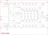
Hi, can anyone please help me to get this Vgs multipier to work OK. I want to have about 200mA idle current.
Currently it works but not so well. With a slow start it stabilizes nice. With a fast power on the idle rushes up. Also it is quite sensetive to mains voltage. A few V up and it will rush, a few V down it will not idle.
Some tips on how to design the Vgs multiplier for this purpose would be helpful.
- Ulf
Attachments

Hi, can anyone please help me to get this Vgs multipier to work OK. I want to have about 200mA idle current.
Currently it works but not so well. With a slow start it stabilizes nice. With a fast power on the idle rushes up. Also it is quite sensetive to mains voltage. A few V up and it will rush, a few V down it will not idle.
Some tips on how to design the Vgs multiplier for this purpose would be helpful.
- Ulf
Hi Ulf,
I'm not eager to comment on your OPS design, but please see a good OPS, based on the same IRFP240/9240 HexFETs with bias tracking, close to ideal, here:
http://www.diyaudio.com/forums/soli...t-end-going-high-tech-smd-10.html#post4280922
Please note, that the drivers are located at the separate local heatsink, together with Q19. Q23 is located on the mail heatsink, tracking the temperature of the output pairs. A so called dual-point bias spreader.
Cheers,
Valery
Part of the joy of the traditional approach, which installs series resistors between the follower transistors and the output node, is that it makes biasing easier. With resistors, you design the bias network to create a designer-chosen voltage across these resistors. When you know the voltage V and you know the resistance R, Ohm's Law gives you the current: I=V/R. Voila! Bias current is controlled.
Nelson Pass has designed a cute variation of this called "Optical Bias" which uses an optoisolator to sense the voltage across these resistors and control the biasing circuit so that V_across_resistors remains constant. Douglas Self has designed a different cute variation in his Trimodal amplifier, which senses the voltage across the resistors using a discrete transistor differential amplifier.
Nelson Pass has designed a cute variation of this called "Optical Bias" which uses an optoisolator to sense the voltage across these resistors and control the biasing circuit so that V_across_resistors remains constant. Douglas Self has designed a different cute variation in his Trimodal amplifier, which senses the voltage across the resistors using a discrete transistor differential amplifier.
Thanks for the reponses.
Source resitors is not what I want to use. With 200mA bias current I would need about 20 Ohm on each source. So the output impedance would be in the 40 Ohm range - not OK.
Valery - yes I see that you have done and will check out this further. A bit over my head, but I will take some time to try and understand the circuit.
Maybe CCS on the top and bottom of my original bias circuit would work?
-Ulf
Thanks for the reponses.
Source resitors is not what I want to use. With 200mA bias current I would need about 20 Ohm on each source. So the output impedance would be in the 40 Ohm range - not OK.
Valery - yes I see that you have done and will check out this further. A bit over my head, but I will take some time to try and understand the circuit.
Maybe CCS on the top and bottom of my original bias circuit would work?
-Ulf
Hi Ulf,
Just noticed, the link in my previous post points on the quasi-complimentary option. Here is the right one 😉
Attachments
Hi Valery,
I have been looking at your site. Maybe I need to do as you mention regarding your drive stage - use 2 bias circuits. One for the basic bias and one for temperature compensation.
I did read up on the Vbe multiplier and managed to build a working one. This did work but it over compensated. So the bias moved toward zero as the amp was warming up. I had to adjust it to keep it at reasonable levels. With this in mind I did not dare to try a cold start after that. I have already fried some mosfets.
Previously I tried a bias circuit with a LM329 and a trim-pot that gave a nice start-up behaviour, not especially sensitive to rail voltage, but it did drift some (but rather slow) during warm up.
So now I am thinking about combining this with a Vbe multiplier to reduce the drift.
But maybe this is all futile. I am hoping that the Spice models are accurate at low currents. In that case I shoud be able to get a decent output impedance with 2-300mA idle. But it will need to me measured of course.
Best Regards: Ulf
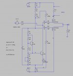
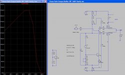
I have been loking at the bias circuit that you showed me Valery. After some modifications of values, and components that I have available, to get the idle current I am wanting I ended up with this circuit.
If I replace Q2, R16, R17 with a voltage source (to simulate that this is not thermally coupled to the sink) I get this Bias vs Temp behavior.
mV in the graph equals mA idle current. If we factor in that Q2 will be a bit heated as well the temp coeficient should be more negative. So this might work.
Any thoughts?
-Ulf
Attachments
Hi Ulf
I think your problem is due to the high value of R7 and R8.
I can see that you feed the signal in throug C2 and C3 and that you therefore want a high input impedance, but 1.2 Mohm is waaaay to high for the high Ciss of the lovely MOSFETs. That is the reason for your troubles.
In similar circuits in ready-made hifi ( Pioneer, Sony etc) the idle current in the bias scheme is a few mA, and Rod Elliot argues it should be 13mA or above, to feed the MOSFETs with enough current to properly control the gates and their input capcaitance.
By isolating with 1.2Mohm there is absolutely no control of the bias.
Have you tried to lower R7 + R8? ...1k?...10k?
Personally i use 0 ohms but my driver-circuit is connected directly to the bases of the output.
Your first bias scheme should be okay, and you can do without source resistors, even though they do make life a bit easier.
Hi Henrik,
no the bias resistors are not the problem. But I could use smaller bias resitors. 100k or something would not be much load on the gain stage. I have tried different values with the same result. I have also built a couple of smaller versions of this stage with other mosfets and 25V rails that works OK and idle steady at 250mA even without temperature compensation.
The problem is that I want to run the mosfets with rather high bias 200-300mA to get a low output impedance.
That heats up the mosfets and when they get hot the bias current goes up. Without compensation they will just continue to rise and eventually blow.
So I need a bias circuit that compensates and gradually lower the bias as the Mosfets gets warmer. Best would be some form of current sensing, but i dont know how that could be done in a simple way. The more common temperature compensation I hope could be good enough. But I need to build it and test. Sink size, position of sensor BJT and so on need to be tuned to work properly and stable.
-Ulf
- Status
- Not open for further replies.
- Home
- Amplifiers
- Solid State
- Biasing of MOSFET output buffer