Hi Guys,
I have a hard time to chose the correct components, can some of you please advice on BEST possible Inductors and Capacitars UF value for the Seas Woofer CA26RFX H1305 (Link: Data sheet - H1305-08 - Loudspeaker Freaks)
I want to for BASS only to my 3-Way speakers. Maybe it will make more sonic sance do not use inductors and capacitors at all and just connect them to speakers terminals!?
Here is what I have:
So here is what I have now;
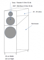
1). Tweeters: Seas (Seas 29TFF/W H1318-06) 6 Ohm, 92 db (Seas 29TFF/W H1318-06 Tweeter - Prestige Series)
2) Mid-Bass: KEF - (SP1193) 8 Ohm, 90 db (http://i.ebayimg.com/00/s/NzcxWDEwNTc=/z/KwIAAOSw9N1VyRVF/$_1.JPG) Taken from these speakers: Explore KEF - Cara, Cara Compact - KEF United Kingdom
Now the Mid-bass (KEF) is only cut from the tweeter with 10UF - and not cut towards the Bass. should I keep it this way (it is in its own enclosure of 22 Litres)? Will it be better if I cut it or should I cut the Seas Bass from the Mid-Bass?
Here are the options if it helps for the Seas Bass Woofer:
Audio Inductor AC125 Sup. Super Power Air Core 2.51mH - 3.00mH
Audio Crossover Inductor 2.51mH - 3.00mH AC125 from Falcon Acoustics, The Leading Supplier of DIY Hifi Components.
Audio Inductor AC125 Sup. Super Power Air Core 3.51mH - 4.00mH
Audio Crossover Inductor 3.51mH - 4.00mH AC125 from Falcon Acoustics, The Leading Supplier of DIY Hifi Components.
Audio Inductor AC125 Sup. Super Power Air Core 2.26mH - 2.50mH
Audio Crossover Inductor 2.26mH - 2.50mH AC125 from Falcon Acoustics, The Leading Supplier of DIY Hifi Components.
Many many thanks!
I have a hard time to chose the correct components, can some of you please advice on BEST possible Inductors and Capacitars UF value for the Seas Woofer CA26RFX H1305 (Link: Data sheet - H1305-08 - Loudspeaker Freaks)
I want to for BASS only to my 3-Way speakers. Maybe it will make more sonic sance do not use inductors and capacitors at all and just connect them to speakers terminals!?
Here is what I have:
So here is what I have now;
1). Tweeters: Seas (Seas 29TFF/W H1318-06) 6 Ohm, 92 db (Seas 29TFF/W H1318-06 Tweeter - Prestige Series)
2) Mid-Bass: KEF - (SP1193) 8 Ohm, 90 db (http://i.ebayimg.com/00/s/NzcxWDEwNTc=/z/KwIAAOSw9N1VyRVF/$_1.JPG) Taken from these speakers: Explore KEF - Cara, Cara Compact - KEF United Kingdom
Now the Mid-bass (KEF) is only cut from the tweeter with 10UF - and not cut towards the Bass. should I keep it this way (it is in its own enclosure of 22 Litres)? Will it be better if I cut it or should I cut the Seas Bass from the Mid-Bass?
Here are the options if it helps for the Seas Bass Woofer:
Audio Inductor AC125 Sup. Super Power Air Core 2.51mH - 3.00mH
Audio Crossover Inductor 2.51mH - 3.00mH AC125 from Falcon Acoustics, The Leading Supplier of DIY Hifi Components.
Audio Inductor AC125 Sup. Super Power Air Core 3.51mH - 4.00mH
Audio Crossover Inductor 3.51mH - 4.00mH AC125 from Falcon Acoustics, The Leading Supplier of DIY Hifi Components.
Audio Inductor AC125 Sup. Super Power Air Core 2.26mH - 2.50mH
Audio Crossover Inductor 2.26mH - 2.50mH AC125 from Falcon Acoustics, The Leading Supplier of DIY Hifi Components.
Many many thanks!
Attachments
Last edited:
You need to do some crossover design. 🙂
1 - Mount your drivers
2 - Measure FR and impedance in place for each.
3 - Calculate acoustic offsets from tweeter plane
4 - Import data to XSim or similar.
5 - Design your crossover
6 - Build.
1 - Mount your drivers
2 - Measure FR and impedance in place for each.
3 - Calculate acoustic offsets from tweeter plane
4 - Import data to XSim or similar.
5 - Design your crossover
6 - Build.
You need to do some crossover design. 🙂
1 - Mount your drivers
2 - Measure FR and impedance in place for each.
3 - Calculate acoustic offsets from tweeter plane
4 - Import data to XSim or similar.
5 - Design your crossover
6 - Build.
Hi, to be hones it`s a dark forest for me as being not that much technical in it. By looking at the Seas Woofer PDF is it possible to tell the parts needed from its specifications? I don`t use a crossover PCB board, only point to point soldering.
Kind Regards
Your whole project is ill-conceived. 😱
A 10" bass with an 8" as mid is just not how you build a three way. 😕
This is nearer how it's done:
Jenzen CA
You have the parts for a decent 8" two way there in about 25-30 litres closed box.
Like below. AFAIK, the same Elac bass. Quite decent bass response.
A 10" bass with an 8" as mid is just not how you build a three way. 😕
This is nearer how it's done:
Jenzen CA
You have the parts for a decent 8" two way there in about 25-30 litres closed box.
Like below. AFAIK, the same Elac bass. Quite decent bass response.
Attachments
Your whole project is ill-conceived. 😱
A 10" bass with an 8" as mid is just not how you build a three way. 😕
This is nearer how it's done:
Jenzen CA
You have the parts for a decent 8" two way there in about 25-30 litres closed box.
Like below. AFAIK, the same Elac bass. Quite decent bass response.
Hi,
I heard the KEF 8 Inch Mid-Bass in original design and I did like it very much it gives good mid bass, I mean was really good to me. Now, the problem was a lack of Bass that is why I decided to use them as they are in a the Mid section and just add a bass woofer to solve the problem. Don`t get me wrong, I just can not understand the problem of using the KEF as mid frequency as it is doing that job very well. Should I not cut it to its lower signal with capacitor and let the Woofer take care of the rest at the lower registry. Logically that make sense to me. If I was to leave the Woofer without cutting it, by directly connecting it to speaker terminals would that be better than using capacitors and inductors with bass woofer?
The main benefit of a three way is you can use a small efficient 4" or 5" mid with good dispersion and low breakup up to 3.5kHz and spare it large bass excursion.
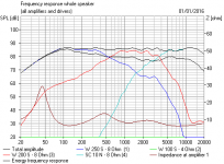
I don't know why you are suddenly discovering a lack of bass end from that paper 8" unit. Perhaps you are running it filterless, which will make it sound horrible.

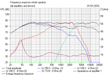
Below is the sim with a regular 2nd order filter as above. 3dB of bafflestep, aka bass boost. About right for a speaker close to a wall.
A three way, especially with 8" mid, is a much more demanding proposition. Probably beyond your abilities.
I don't know why you are suddenly discovering a lack of bass end from that paper 8" unit. Perhaps you are running it filterless, which will make it sound horrible.
Below is the sim with a regular 2nd order filter as above. 3dB of bafflestep, aka bass boost. About right for a speaker close to a wall.
A three way, especially with 8" mid, is a much more demanding proposition. Probably beyond your abilities.
Attachments
Hi Steve,
Thanks for your quick and detailed reply. Eventually I will learn to understand the crossovers better.
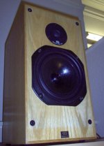
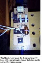
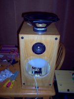
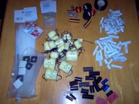
Can you please have a look for me at my chosen woofer and I also took a picture of my crossover that you could have a better ideas of what it all looks like.
10 Inch Seas woofer I decided to use:
1). Seas CA26RE4X H1316 Woofer - Prestige Series 90.5 db
http://www.falconacoustics.co.uk/downloads/Seas/h1316_datasheet.pdf
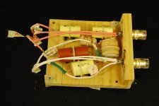
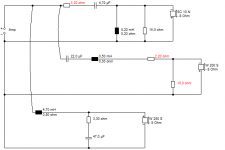
I have attached my point to point soldered crossover. It looks as it has 3rd order Tweeter 3rd order for Mid-Bass.
1). The Tweeter used with Two Capacitors of - 7uF
2). The Mid-Bass used with 10uF cross for High Frequency and 22uF for Low Frequency
3). The Bass needs to be decided... As well as best suited Litres.
Will any of these iductors be suitable:
Audio Inductors 0.01mH - 10.00mH, Ferrite, Air Cores, Iron Dust.
Audio Inductor AC125 Sup. Super Power Air Core 2.51mH - 3.00mH
Audio Crossover Inductor 2.51mH - 3.00mH AC125 from Falcon Acoustics, The Leading Supplier of DIY Hifi Components.
Audio Inductor AC125 Sup. Super Power Air Core 3.51mH - 4.00mH
Audio Crossover Inductor 3.51mH - 4.00mH AC125 from Falcon Acoustics, The Leading Supplier of DIY Hifi Components.
Audio Inductor AC125 Sup. Super Power Air Core 2.26mH - 2.50mH
Audio Crossover Inductor 2.26mH - 2.50mH AC125 from Falcon Acoustics, The Leading Supplier of DIY Hifi Components.
Am I right to think that 75 Litres is best for the Woofers?
Can you please have a look at inductors and capacitors value to have this woofer crossed in its best usable frequency.
Many Thanks, I really appreciate your advice.
Mykhailo
Thanks for your quick and detailed reply. Eventually I will learn to understand the crossovers better.
Can you please have a look for me at my chosen woofer and I also took a picture of my crossover that you could have a better ideas of what it all looks like.
10 Inch Seas woofer I decided to use:
1). Seas CA26RE4X H1316 Woofer - Prestige Series 90.5 db
http://www.falconacoustics.co.uk/downloads/Seas/h1316_datasheet.pdf
I have attached my point to point soldered crossover. It looks as it has 3rd order Tweeter 3rd order for Mid-Bass.
1). The Tweeter used with Two Capacitors of - 7uF
2). The Mid-Bass used with 10uF cross for High Frequency and 22uF for Low Frequency
3). The Bass needs to be decided... As well as best suited Litres.
Will any of these iductors be suitable:
Audio Inductors 0.01mH - 10.00mH, Ferrite, Air Cores, Iron Dust.
Audio Inductor AC125 Sup. Super Power Air Core 2.51mH - 3.00mH
Audio Crossover Inductor 2.51mH - 3.00mH AC125 from Falcon Acoustics, The Leading Supplier of DIY Hifi Components.
Audio Inductor AC125 Sup. Super Power Air Core 3.51mH - 4.00mH
Audio Crossover Inductor 3.51mH - 4.00mH AC125 from Falcon Acoustics, The Leading Supplier of DIY Hifi Components.
Audio Inductor AC125 Sup. Super Power Air Core 2.26mH - 2.50mH
Audio Crossover Inductor 2.26mH - 2.50mH AC125 from Falcon Acoustics, The Leading Supplier of DIY Hifi Components.
Am I right to think that 75 Litres is best for the Woofers?
Can you please have a look at inductors and capacitors value to have this woofer crossed in its best usable frequency.
Many Thanks, I really appreciate your advice.
Mykhailo
Attachments
Gotta love it when someone throws three VERY random drivers and a box at you and says "design the rest please" ! 😱
H1316-08 CA26RE4X
OK, that's a 10" reflex driver, so about 50-70L. 3" diameter reflex tube about 6 inches long I suppose. The 8" mid needs 20-30L closed box.
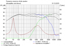
It all modelled quite well, in fact. I did it usual style and simple style.
SEAS-3-Way-Classic
SEAS Kit 503
The attenuator on the 8 inch mid keeps impedance easy, so well-behaved frequency response. It's really a two way with an extra bass added on.
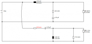
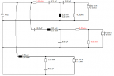
If I was you, I'd make the top box or mid baffle removeable in case you want to change the mid later, but here's what I got. Red resistors adjust level. Just buy cheap crossover components. 250V polypropylene caps and ferrite cores for the big values. Air coil for the 0.2mH. NP electrolytic for the 47uF.
Components
H1316-08 CA26RE4X
OK, that's a 10" reflex driver, so about 50-70L. 3" diameter reflex tube about 6 inches long I suppose. The 8" mid needs 20-30L closed box.
It all modelled quite well, in fact. I did it usual style and simple style.
SEAS-3-Way-Classic
SEAS Kit 503
The attenuator on the 8 inch mid keeps impedance easy, so well-behaved frequency response. It's really a two way with an extra bass added on.
If I was you, I'd make the top box or mid baffle removeable in case you want to change the mid later, but here's what I got. Red resistors adjust level. Just buy cheap crossover components. 250V polypropylene caps and ferrite cores for the big values. Air coil for the 0.2mH. NP electrolytic for the 47uF.
Components
Attachments
Hi Steve, just a quick question,
Is the Seas Woofer H1316 you mentioned above is better suited than the one I thought which is this one: (Seas H1305)
Data sheet - H1305-08 - Loudspeaker Freaks
Thanks
Is the Seas Woofer H1316 you mentioned above is better suited than the one I thought which is this one: (Seas H1305)
Data sheet - H1305-08 - Loudspeaker Freaks
Thanks
Hi Steve, just a quick question,
Is the Seas Woofer H1316 you mentioned above is better suited than the one I thought which is this one: (Seas H1305)
Data sheet - H1305-08 - Loudspeaker Freaks
Thanks
Your original:
H1305-08 CA26RFX
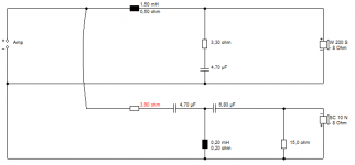
Your later idea:
H1316-08 CA26RE4X
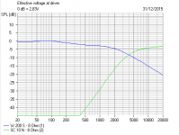
You can expand the Frequency response at SEAS and tab between them to see the difference. The first one needs a 1mH bass coil at least to be flat. The second one is a higher inductance woofer with a smaller magnet. It also has a higher Qms at 3.99 which is good for detail. It would run quite well fullrange with no filter or a series crossover IMO.
Nothing in it really. I allowed for the highish inductance on both anyway. Which is a poor answer. I think they'll both sound good.
Hi Steve,
Would it be OK to use 50.00uF Polypropylene Capacitor for the woofer instead of 47uF?
Would it be better go with a bit higher Inductor Air Core 0.21 - 0.25mH or should I stick to 0.20mH only?
Another though I have is that I limit the KEF with 22uF cross, should I remove the 22uF to give it a deeper frequency coverage in its closed enclosure (currently about 20 Litres)?
Thanks
Hi Steve,
Would it be OK to use 50.00uF Polypropylene Capacitor for the woofer instead of 47uF?
Inaudible difference around 3%. So it doesn't matter.
Would it be better go with a bit higher Inductor Air Core 0.21 - 0.25mH or should I stick to 0.20mH only?
Why change the calculated value? But TBH, you could use 3.3uF and 0.3mH in the tweeter filter. It ends up quite similar. Or 3.9uF and 0.25mH if you have them lying around.
Another though I have is that I limit the KEF with 22uF cross, should I remove the 22uF to give it a deeper frequency coverage in its closed enclosure (currently about 20 Litres)?
No. No point in giving an 8" midbass any extra excursion or distortion artefacts. The 10" does the bass.

Last edited:
Hi Steve,
Have a look for me please, am I good to go with these for the Bass woofers (H1305-08);
1). (2) Solen 50.00uF 400V DC Polypropylene Capacitor
Solen 50.00uF 400V DC FastCap Polypropylene Audio Capacitor from Falcon Acoustics, the leading supplier of diy hifi components.
2). (2) AC125 Sup. Super Power Air Core up to 0.20mH Audio Inductor
http://www.falconacoustics.co.uk/ac125-super-super-power-air-core-value-range-0-20mh-audio-inductor.
Should I fill the bass box with polyester hollow fibre of let say 70%?
Thanks
I keep saying that people fret far too much about crossover components. 😀
For the bass section this 50uF 50V NP will be fine.
For the mid section, let's go for a good but compact 22uF 250V MKP since old Troels Gravesen always reckons it matters with mids. I have a huge collection of huge and pricey Maplin 630V "Audio Grade" yellow capacitors, but really I can't hear any difference compared to smaller 250V types.
Baked coils are good for air-core, since the windings are effectively glued and less prone to rattle with vibration, so maybe Wilmslow's loosely wound plastic bobbins can be improved upon. IDK really.
Here's a link to my thoughts on cabinets:
http://www.diyaudio.com/forums/multi-way/223174-interesting-read-i-found-lossy-cabinet-designs-harbeth.html#post3234256
If you want to get prissy, stick some rubbery/corky Regupol damping to the cabinet panels. But a big roll of BAF wadding behind the 8" pressed steel chassis to damp any ringing is a GOOD THING, IMO. BAF doesn't do much to the bass end. It really only stops some midrange shout at around 3kHz.
Attachments

Last edited:
Hi Steve,
In a future I will use a separate cabinet for Mid and Tweeter with same width to the bass enclosure as you rightly adjusted. For now I will be using all in one enclosure that I already build a few years ago which easily gives 60 Litres in closed box for the woofer (I'm happy for that also).
To my understanding, if the inductor has a higher mH value is that means the woofer signal or output volume of a woofer will be lowered?
In case of my 6 Ohm tweeter, I currently use two of 8uF capacitors and unknown to me value the inductor, and they sound a bit louder that I know they should, if I was to change the inductor to the value you recommended of 0.3mH will it lower they output signal? Should I also change 8uF to 4.7uF Isn’t the tweeter frequency will by too narrow in changing the capacitors?
I fact I was thinking and checking some good alternative for Mid drivers (this things become addictive 🙂 what do you think of this one ?http://www.falconacoustics.co.uk/downloads/Seas/h1262_datasheet_.pdf
Thanks
Too many questions and too much mission creep there. 😀
Try a bit of modelling:
Downloads
Import some of these into the projekte folder and have a play:
boxsim-db.de | Boxsim Projektdatenbank
Try a bit of modelling:
Downloads
Import some of these into the projekte folder and have a play:
boxsim-db.de | Boxsim Projektdatenbank
- Status
- Not open for further replies.
- Home
- Loudspeakers
- Multi-Way
- Inductors and Capacitors for Seas Woofer CA26RFX H1305 in 3-Way design