Have just "acquired" a Cambridge A500 amplifier which has a problem in that the left channel is badly distorting all of the time. By judicious swapping around of internal connections it is clear the problem is in the power stage but short of simply replacing all the active components, I'm at a loss as to how to narrow down the diagnosis. Any suggestions most welcome.
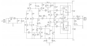
Please find attached schematic of the left channel, signal comes in at the extreme left CN201, power transistors are the SAP 15N and 15P Darlington devices towards the right hand end.
Please find attached schematic of the left channel, signal comes in at the extreme left CN201, power transistors are the SAP 15N and 15P Darlington devices towards the right hand end.
Attachments
Seems there's quite a bit of discussion of this around. I take it the power transistors are the most likely culprits?
ML
ML
Yes, its a very common failure mode, with around 90% of serious amplifier problems being to do with the output stage, where the heat is on, significant currents flow and most thermal stress occurs. It's also where serious mistakes and abuse occur. Add these SAP15 Darlington transistors to the problems there and you have a disaster waiting to happen.Seems there's quite a bit of discussion of this around. I take it the power transistors are the most likely culprits?....
The output devices aren't just single power transistors though. They are obsolete Sanken Darlington transistor types where the driver transistors are included on the chip as well as an array of bias control diodes. They also have 5 pins instead of the usual 3 so when they blow, you have 2 choices:
1. Hope for a miraculous source of NOS parts (i.e. non-fake replacements). Suppliers like Profusion plc. may still stock them or similar SAP16N/P. Don't use Ebay sellers, where there are no guarantees of what you are buying.
2. Convert the amplifier to use external emitter resistors and fit Sanken replacement types STD03N/P in lieu of original SAP15N/P
Sadly, you can't buy any old Darlington transistor and hope it will work. Bias control is difficult enough with Darlingtons and for decent audio, they need to be excellent parts and the thermal coupling needs to be special for reliable bias.
If you aren't confident with properly checking that the output devices really are shot and fitting and adjusting any replacements, consider a pro. repair if you consider the amplifier worth keeping.
Ian &c
Really appreciate yr help.
The simplest choice for me is to replace with SAP 16N/P which seem to be rather more
available than 15s. Can I simply drop these in or does it require any mods to make them fit?
Cheers
ML
Really appreciate yr help.
The simplest choice for me is to replace with SAP 16N/P which seem to be rather more
available than 15s. Can I simply drop these in or does it require any mods to make them fit?
Cheers
ML
Old'n'Cranky has a good point. Normally you could pull out the device and test it a simply a couple of back to back diodes. These are not simple power transistors, however. They are integrated circuits and I would not be confident of their being amenable to such a simple,test.
looking at the circuit diagrams for STD03N and STD03P they seem identical to the SAP15s with the exception of an internal resistor. Is there any reason I couldn't substitute them and use a separate resistor?
I did suggest that mod. back in #4 , as Sanken clients generally had problems with the SAP series and their rather fragile chip emitter resistor. That's the reason why they are obsolete and their STD03 replacements don't have one. You need rather large (3-5W) resistors for the mod. and they need space for air flow, which we're assuming is available.looking at the circuit diagrams for STD03N and STD03P they seem identical to the SAP15s with the exception of an internal resistor. Is there any reason I couldn't substitute them and use a separate resistor?
There are similar threads about this Cambridge A500 problem that could be helpful: http://www.diyaudio.com/forums/solid-state/141454-blown-power-transistor-sap15-cambridge-a500.html
Here's another that might shed some light on the test problem: Cambridge Audio A500 Amplifier - UK Vintage Radio Repair and Restoration Discussion Forum.
Re: testing the SAP series, I can only say its difficult to do at reasonable current without a test jig. I tested the first pair of these I saw in a Musical Fidelity amp IIRC. I was sure these were the culprit in one channel because DC offset was floating at a few volts and there was no bias current. The scope showed plenty of signal at the bases though. In-circuit, that's my quick way to diagnose an open failure, so long as the owner hasn't already wrought havoc by twiddling anything and everything that looks adjustable.
I pulled them, powered them with a bench supply and a few resistors and found the emitter or rather the emitter resistor, was open circuit on the N type. I've not heard of a C-E short with these (normal failure mode) but if the device doesn't test like a Darlington, it's toast anyway.
Most transistor testers can accommodate Darlingtons for simple testing but it may be that some DMMs can't. Because we reallly need to test and match output transistors with more than a few volts and milliamps, we could need to buy or build a suitable test meter for currents up to at least 0.5A. It could double as a matching jig, which will be essential for building or repairing larger amplifiers with multiple output devices

Search for error
As I understand it the amp can be powered up and is "running"?
So before changing any parts and do more speculation is it possible
to show us a picture of the output waveform as seen on a scope?
Please use a sine or triangular input of for instance 1 kHz and tell us
the amplitude of the output waveform as seen on this picture, thanks.
You may want to try and show us different amplitudes in addition.
Does this waveform change with output load? Use a resistor of say
8 ohms (maybe 4 to 16, anything you find) and sufficient wattage.
as_audio flatters me with his thorough suggestion. As a mere engineer I am sadly bereft of a 'scope and so cannot do the required investigation. Nice thought tho, may yet invest in one. Believe they go for peanuts on Ebay
ML
ML
If you want to start investigating your amp and not only speculating you should use a
(borrowed?) scope with function generator as source. True this can be bought cheaply.
So we at least agree that you own a digital voltmeter?
Set the range of the DMM to say 200volts dc, connect the black wire to ground, chassis
for instance, and measure the dc output voltage of the amp (the amp is switched on) at
the red speaker terminal.
I assume that the amp has either no speaker relay or the relay is turned on.
If done so we can proceed.
Please forgive me but I only have an analog voltmeter! This notwithstanding, it should suffice for the purpose you suggest.
I have in hand replacement of the (supposedly defective) 15s with 16s and will try yr suggestion when I next have the box in bits.
There are red LEDs adjacent to the power transistors and the left (defective) channel
diode decays (ie goes out) much more quickly than the right channel. Significant?
ML
I am sadly bereft of a 'scope and so cannot do the required investigation.
Please forgive me but I only have an analog voltmeter!
Sorry I did not find this in post 1..
So this thread is about "my car is broken and I want to repair it, but I don't own a garage
and have no tools. But it probably helps to buy some spare parts in advance and get
help online."
We are not sure by now, but sorry for the expense (did you mention before that you already have these?)I have in hand replacement of the (supposedly defective) 15s with 16s
ML
We probably have to do some additional voltage checks with small voltages, but ..Analog voltmeter! This notwithstanding, it should suffice for the purpose you suggest.
ML
Maybe, maybe not.There are red LEDs adjacent to the power transistors and the left (defective) channel
diode decays (ie goes out) much more quickly than the right channel. Significant?
ML
You surely will get help here. My first advice is to find a local repair man.
My second advice is buy some essential instruments for a cheap price and
find somebody to teach you.
Third is to teach yourself with these instruments, some books and, yes, internet.
Only as a fourth advice I suggest try to do the repair with this analog VOM alone
but be prepared to blow additional parts = learning by doing in the hard way.
If you visit my workshop I will do the repair for free. You will have to pay for additional
advice and teaching only. I can manage that you learn to set up your own repair shop
within a few weeks and earn money with it. Online support is included.
Oh dear I'm clearly a very bad man. My single explanation is that the consensus of (about 6) contributors with similar problems on similar boxes was the power transistors were to blame 'cos its a known problem with these amps.
I'm perfectly happy to test the devices by substitution of two known good parts and see what happens.
If all else fails I can chuck the box, - I got it for free anyway!
I may yet invest in a scope but it all seems too much like hard work. The amp is only a spare anyway.
Cheers
ML
I'm perfectly happy to test the devices by substitution of two known good parts and see what happens.
If all else fails I can chuck the box, - I got it for free anyway!
I may yet invest in a scope but it all seems too much like hard work. The amp is only a spare anyway.
Cheers
ML
Have just checked Ebay and found a vintage scope for a tenner (GBP) so cost not a prob. In the process found this:
DSO138 2.4" TFT Digital Oscilloscope DIY Kit Parts Probe Learning 1Msps BL P3VY | eBay
portable handheld scope kit. Looks sexy, anybody have thoughts as to its actual useability?
Cheers
ML
DSO138 2.4" TFT Digital Oscilloscope DIY Kit Parts Probe Learning 1Msps BL P3VY | eBay
portable handheld scope kit. Looks sexy, anybody have thoughts as to its actual useability?
Cheers
ML
When you have pcb removed from cabinet ...... take magnifying glasses and also resolder any solder joint that looks cracked, which could be all of the solder joints in a 18 year old amplifier known to have heat issues. Also not as sexy as active components, 1998/1999 chinese electrolytics in an amp known to have heatissues..... your opening question excludes everything but active components
My single explanation is that the consensus of (about 6) contributors with similar problems ...
ML
Not quite a consensus. Read again: Cranky recommended to test it.
Irrebeo hinted that the problem may be elsewhere.
KDad gave input where to find the SAPs, waste of time if you already had them.
I gave some (as I thought) useful advice in posts 12 and 14.
Not sure you want to work it out or not.
Additional question: is the bottom plate detachable? Sometimes it is not in todays products.
Have just checked Ebay and found a vintage scope for a tenner (GBP) so cost not a prob. In the process found this:
DSO138 2.4" TFT Digital Oscilloscope DIY Kit Parts Probe Learning 1Msps BL P3VY | eBay
portable handheld scope kit. Looks sexy, anybody have thoughts as to its actual useability?
Cheers
ML
For beginners I recommend a used tabletop scope. In Germany Hameg is preferred.
Prices may be less than 40 E.
Last edited:
- Status
- Not open for further replies.
- Home
- Amplifiers
- Solid State
- Cambridge Distorting