Hello all,
I am new to this site and I have read through posts by searching.
All i know is soldering parts together by looking at a circuit diagram and basic electrical principles.
I am building a new car audio setup with
Kicker Zx 1500.1
Kicker Zx 650.4
Kicker S12 L7
Kicker RS 65.2
Kicker DS 6930
The amp was only installed two days back and it was working fine.
Today afternoon while leaving from work the audio system was working fine. While driving I switched off the HU and switched it back on after 30 secs.
Thats when i heard the boom and smoke... After the initial shock I switched off the HU.
When i plugged it back it the amp is switching on I guess but no output.
I opened to see what went wrong and so far visually this is visible
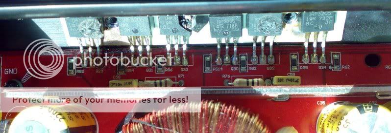
Those are IRF 3205's
I planning to order them online. It will be really helpful if i need to check anything else or if i am wasting time on this
What i dont understand is why it got blown? Do to the heat?
Its around 40 degree outside temp and car was parked in the sun.
As you can see the MOSFET was cracked open.
I am new to this site and I have read through posts by searching.
All i know is soldering parts together by looking at a circuit diagram and basic electrical principles.
I am building a new car audio setup with
Kicker Zx 1500.1
Kicker Zx 650.4
Kicker S12 L7
Kicker RS 65.2
Kicker DS 6930
The amp was only installed two days back and it was working fine.
Today afternoon while leaving from work the audio system was working fine. While driving I switched off the HU and switched it back on after 30 secs.
Thats when i heard the boom and smoke... After the initial shock I switched off the HU.
When i plugged it back it the amp is switching on I guess but no output.
I opened to see what went wrong and so far visually this is visible
Those are IRF 3205's
I planning to order them online. It will be really helpful if i need to check anything else or if i am wasting time on this
What i dont understand is why it got blown? Do to the heat?
Its around 40 degree outside temp and car was parked in the sun.
As you can see the MOSFET was cracked open.
The amp would not have powered up if it was too hot. Most amps will operate up to ~80C.
After removing the power supply FETs, confirm that all of the gate resistors are within tolerance (±5% of printed value - 101 = 100 ohms, 680 = 68 ohms).
You also need to check the output transistors to determine if any have failed. You should not read anything near 0 ohms between any of the legs of any individual transistor. The outputs are the larger transistors diagonally across from the power supply transistors.
It's likely that the other power supply has also failed. The six FETs next to the ones that burned are the ones for the other supply. Again... You should not read anything near 0 ohms between any of the legs of any individual transistor.
Also check the driver transistors (Q24-Q27). You should pull them out of the circuit to check them.
If you don't know how to check transistors, use the links on the following page. The drivers are bipolar transistors. The rest are FETs.
http://www.bcae1.com/repairbasicsforbcae1/images/transistortestpage02.html
Thank you.
I will post picture of the complete amp just in case I cant find the other FETs and driver transistors.
I have been reading up bcae1.com and its from there i reached here.
I will update whats going.
I will post picture of the complete amp just in case I cant find the other FETs and driver transistors.
I have been reading up bcae1.com and its from there i reached here.
I will update whats going.
Hi to all.Repaired one like this like 4 months ago,was easy job.In my case all IRF3205 were blown,because of two shorted IXTQ36N30 in output stage.Replaced all IRF3205,gates resistors,and also four drivers transistors ,they were two pair of 2SD667 and 2SB647 from HITACHI ,they are hard to find.Replaced them with BC640 and BC639 ,they have almost same specification.For output stage is great substitute FQA38N30 from Fairchild or even better to install FQA44N30 they can handle more current.Mosfets from Ixys are hard to find and they are more expensive.Amp is working great until now
I have ordered the 15 units of 3205's just incase..
How did it happen in your case? (switching on, Play at full load, short on speaker side)
Was it a kicker 1500.1 amplifier?
Was there any visible signs on the FET's and other transistors that they were blown? How did u find out what was blown?
Lets say my FETs are replaced and issue resolved. Will the amp perform like a new one?
I am also keeping my options open for a refurbished Kicker 1500.1 if this fails.
My amp was exactly ZX1500.1.To repair this amp you have to follow step by step .1 Remove all IRF3205 2.Measure the resistance all of gate resistors +-3% it is ok,but better to replace them.3After replaicing all resistor (w/o mosfets) put negative probe of the meter to the ground (drain of the mosfet or negative power terminal) it is show you the resistance,if I remember right,about 47k.If it out ,probably driver transistors broken.Have to replace them.4.After this you can try to power up amp w/o mosfets,to see what voltage you have on the gates and waveform(you need osciloscope),if you don't have one and you replaced driver transistors everything should be fine(usually TL494 survived in most cases) Meter shoud read on all gates like 6,25 to 6,50V.Do this first ,then we will continue.My amp probably get broken of the poor soldering.If you repair it in right way,it will work like brand new
I fixed a ZX1000.1 before with the help from the guys over here. you can find the thread in here somewhere.
I got mine broken and gambled on trying to get it fixed so I could have a high powered amp for cheap. and it paid off. 😉
basically, on mine, all PS fets blew and output inductor was fried. luckily, all drivers are good and output transistors were good too.
it seems that kicker never uses PS fetsfrom the same batch. mine was also that way. could have contributed to the failure because Fets that aren't from the same batch when operated in parallel don't share current very well.
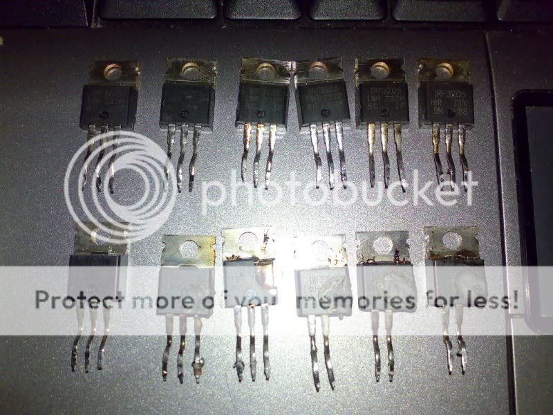
Today I decided to remove all those 12 fets.
And test the circuit but i got tried by removing them.
The quality of the board is not all that great.
The solder used is again terrible.
I would say even the design of the circuit is bad.
Maybe its just be but I had a hard time removing them.
Used a good quality lead to solder to fill them and then used the pump to remove them.
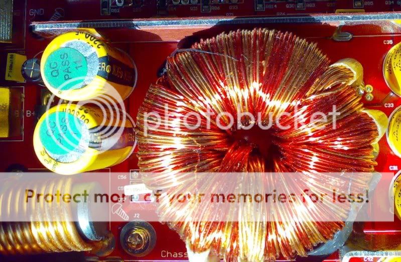
CAn someone tell me where to find the output inductor
Picture of the FETs. Different batch as observed.
And test the circuit but i got tried by removing them.
The quality of the board is not all that great.
The solder used is again terrible.
I would say even the design of the circuit is bad.
Maybe its just be but I had a hard time removing them.
Used a good quality lead to solder to fill them and then used the pump to remove them.
CAn someone tell me where to find the output inductor
Picture of the FETs. Different batch as observed.
The one inductor near to the fets.
Is this the one?
How do i know its blown? Its basically a coil right?
Is this the one?
How do i know its blown? Its basically a coil right?
If you apply enough new solder to allow the soldering iron to heat all 3 leads at once when the tip of the iron is laid across the leads, the transistors will almost fall out on their own. If they require any force to remove them, it will be minimal and it will be nearly impossible to damage the board.
Use the desoldering pump to remove the solder from the vias only after the transistors have been removed.
Use the desoldering pump to remove the solder from the vias only after the transistors have been removed.
Hey i know these posts are kinda old but maybe somone will see this. I need to replace my irf3205's aswell but there are a couple differant choices at digikey. Which one is the one i want?
Ditto, I know the thread is old too, but can anyone assist with getting hold of a circuit diagram?
Sorry Ditto, the diagrams are not available, however if you need any help I am a Kicker repair tech and will be glad to guide you through the repair.
What issues are you having with this amp?
Post good quality pics of board so I can determine the model year of amp.
Also, you should start a new thread
What issues are you having with this amp?
Post good quality pics of board so I can determine the model year of amp.
Also, you should start a new thread
Hey Papa, thanks for responding so quickly.
All I know so far is nil output. I haven't got my hands on the amp yet and was merely trying to prepare by obtaining a manual.
If I require more assistance, I'll start a new thread.
All I know so far is nil output. I haven't got my hands on the amp yet and was merely trying to prepare by obtaining a manual.
If I require more assistance, I'll start a new thread.
Need help for my kicker zx1000.1
I don't know how to start a new thread or maybe not allowed because i'm new here. Hoping this way will work. I have read a lot about you so now I attempt this questions to be answered by the specialist.
I found a busted/exploded NTP16N06 (I found the value from one of your reply sir) so I order the replacement for this which you have directed us also to a mouser. Also, I need to know the value of a cracked diode(D27) beside Q13.
So, for my question sir, If ever I already have the mentioned parts, do i have to check or look for more that is possibly causes the problem before soldering the new parts? Visually, eveything is clean except for the Q12, Q13 and D27.
I'm not a full pledge technician but I have an extensive experience of doing electronics so let me try If I can fix this one with your help.
Thank you so much for the in depth explanations you made from several threads here.. I actually learned more here than my prof, LOL!
Sorry Ditto, the diagrams are not available, however if you need any help I am a Kicker repair tech and will be glad to guide you through the repair.
What issues are you having with this amp?
Post good quality pics of board so I can determine the model year of amp.
Also, you should start a new thread
I don't know how to start a new thread or maybe not allowed because i'm new here. Hoping this way will work. I have read a lot about you so now I attempt this questions to be answered by the specialist.
I found a busted/exploded NTP16N06 (I found the value from one of your reply sir) so I order the replacement for this which you have directed us also to a mouser. Also, I need to know the value of a cracked diode(D27) beside Q13.
So, for my question sir, If ever I already have the mentioned parts, do i have to check or look for more that is possibly causes the problem before soldering the new parts? Visually, eveything is clean except for the Q12, Q13 and D27.
I'm not a full pledge technician but I have an extensive experience of doing electronics so let me try If I can fix this one with your help.
Thank you so much for the in depth explanations you made from several threads here.. I actually learned more here than my prof, LOL!

- Status
- Not open for further replies.
- Home
- General Interest
- Car Audio
- Kicker ZX 1500.1 Smoked