Hi guys, i built a simple se amp last year and i'm very happy with the whole thing. . .
However, i fitted a yellow led light into the front panel as a power on indicator but never got round to wiring it in, my question is how?
What do i wire the two leads to and is there a resistor needed etc?
Thanks.
However, i fitted a yellow led light into the front panel as a power on indicator but never got round to wiring it in, my question is how?
What do i wire the two leads to and is there a resistor needed etc?
Thanks.
All depends what you want to wire it to. If it is a typical yellow LED, figure 2.2V @ 20mA or so. You can wire it to a 6.3VAC heater wiring using a 220 ohm resistor. It will flicker at 60Hz. If that bothers you, you'll need a low voltage DC supply of some kind.
If you can't tap from a DC point in the circuit and don't want the flicker use a full-wave bridge and a cap...(don't forget the led series resistor as well)... or, you could use a resistor and a dual color led (say red and green) wired in anti-parallel. It'll glow "yellow" on AC...
If you want to run off the line voltage (120VAC) use a 0.47uF, 200V cap in one leg of the AC line. Put a 1K resistor in the other AC leg. Use a 1N4004 (or such) diode wired in anti-parallel with the led. Put one leg of the AC on one side of the diode pair and the other AC leg on the other side of the diode. Still going to "flash" at 60 Hz (though you'll only see the flash if you wave your fingers in front of it or shake your head around while staring at it)...
If you want to run off the line voltage (120VAC) use a 0.47uF, 200V cap in one leg of the AC line. Put a 1K resistor in the other AC leg. Use a 1N4004 (or such) diode wired in anti-parallel with the led. Put one leg of the AC on one side of the diode pair and the other AC leg on the other side of the diode. Still going to "flash" at 60 Hz (though you'll only see the flash if you wave your fingers in front of it or shake your head around while staring at it)...
Hi there-
I have a tubelab sse power indicator question, so I figured just add it to this old thread and keep it all together.
A friend and I are wrapping up our SSE builds, and he wanted to add a 6.3v pilot lamp from parts express as a power indicator, and I was going to do something similar with an LED.
Per Russ's advice above, for the 6.3v incandescent lamp my friend has, does that mean he just adds it into the two "T1-GRN" terminal blocks (one wire into each) on the board and that's it? I know this is a really simple question, but just wanted to double check before something explodes.
In my case, if I'm going the LED route, I use the same two terminals, but wire a 220 ohm resistor in series with the LED?
I just want to double check that with this sort of wiring, I'm using just terminal blocks, not connecting one end to the board and the other to ground or something. (This has been a great learning process, but still remember blowing up a multimeter back in high school...)
Thanks as always for the help!
Pete
Per Russ's advice above, for the 6.3v incandescent lamp my friend has, does that mean he just adds it into the two "T1-GRN" terminal blocks (one wire into each) on the board and that's it? I know this is a really simple question, but just wanted to double check before something explodes.
In my case, if I'm going the LED route, I use the same two terminals, but wire a 220 ohm resistor in series with the LED?
Pete:
As far as I know, the answer to both your questions is :'Yes".
Wire the incandescent bulb across the heater supply, and do the same with an LED and a suitable dropping resistor.
A comment about some of the jewel-type indicator lights: I bought a bunch of new jewel light holders (imitations of the ones from the 50s & 60s) which use a #47 bulb- I can't rcall if I got them from PartsExpress or another supplier. The lamps in the new holders are shorter than the 'vintage' ones and it's almost impossible to remove the lamp ('push and turn') as it's buried in the holder. So my advice would be to check the lamp removal and insertion process before committing to a particular holder in an amp. BTW, I solved the problem with the jewel holder by replacing the lamp and lamp socket with a large LED and dropping resistor.
When powering an LED from an AC source, beware that many LEDs cannot handle much reverse voltage. For example, my favourite red LED, the HLMP-D101, can only handle 5 V reverse voltage. A 6.3 V AC source imposes 8.9 V peak - a good 180 % of the rated absolute maximum.
To avoid excessive reverse voltage, use a diode such as 1N4148 or 1N400x in anti-parallel (i.e. anode of diode to cathode of LED) with the LED to limit the reverse voltage.
I usually run a standard red, green, or yellow LED at 5-10 mA. Going above that provides very little additional light. For low-current (high-efficiency) LEDs and blue LEDs, consult the data sheet for the LED.
Tom
Last edited:
Thanks so much VictoriaGuy and Tom - exactly what I needed to know, and more...
Much appreciated.
Much appreciated.
On my tube amps I always wire LED to B+.
This also gives indication that B+ is at a lethal voltage when you are working on it.
LED's require series resistor.
You can work out resistor by B+/0.01amps gives resistor value.
This also gives indication that B+ is at a lethal voltage when you are working on it.
LED's require series resistor.
You can work out resistor by B+/0.01amps gives resistor value.
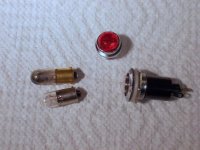
A comment about some of the jewel-type indicator lights: I bought a bunch of new jewel light holders (imitations of the ones from the 50s & 60s) which use a #47 bulb- I can't recall if I got them from PartsExpress or another supplier. The lamps in the new holders are shorter than the 'vintage' ones and it's almost impossible to remove the lamp ('push and turn') as it's buried in the holder.
Here's a pic with the jewel holder with the supplied lamp and a 'vintage' (long) lamp to compare with the 'modern' replacement. You need very sticky fingers (Spiderman??) to remove the short lamp from the holder.
BTW, beware: some lamps being sold as #47 (at inflated prices) are not the long type but the shorter replacement.😡
Fortunately I have a good supply of lamps salvaged from old radio hi-fi gear.🙂 It's surprising how many of them still work, once the dust and tobacco tar are cleaned from them.
Attachments
Interesting idea- what watt rating do you usually use on that dropping resistor? (Seems like a hefty resistor is needed for that little job?)On my tube amps I always wire LED to B+.
This also gives indication that B+ is at a lethal voltage when you are working on it.
LED's require series resistor.
You can work out resistor by B+/0.01amps gives resistor value.
Calculate the dissipated power: P = (V^2)/R
V is the B+ voltage.
Pick a resistor with a power rating of 3-5x the dissipated power, P.
You'll probably find that you need a 3 W or 5 W type. You'll also find that using a high-efficiency LED helps on the power rating of the series resistor as the high-efficiency LEDs will light at 1-2 mA of current rather than the 5-10 mA needed for a regular LED.
Note that even if the LED is extinguished, the B+ can still be charged to significant (lethal) voltage.
I do question the practice of running wires with B+ on them through the chassis to the front panel, just to power an LED, though. I'd prefer using a filament supply for that.
Tom
Last edited:
Calculate the dissipated power: P = (V^2)/R
V is the B+ voltage.
Pick a resistor with a power rating of 3-5x the dissipated power, P.
You'll probably find that you need a 3 W or 5 W type.
I was thinking along those lines -
Dropping 350-400 volts at 10 mA, and using 3-5X the dissipated power as the resistor rating....doesn't that get a bit silly just to power an LED? (10W to 20W power resistor?)
As you say, a lower current LED would help the situation. Like you, I don't fancy running the B+ to the front panel, either.
I suppose it depends on the space in your chassis and your collection of power resistors. It IS a hobby, after all!🙂
When I'm working on amps, I use a meter to check the state of charge of the filter caps, and I discharge them with a "Sparkpen Capacitor Discharge Pen" from the online auction site, or a homebrew version of the same thing, so I don't feel the need for an indicator lamp, though I'm sure I could get used to it if I fitted them.😀
I like the neon indicators that go right on the 120v line (since the power light is usually next to the switch, and if using a double-pole switch, the 120v is available), but I've run out of good holders for the bulbs.
Attachments
As you say, a lower current LED would help the situation. Like you, I don't fancy running the B+ to the front panel, either..
You don't run B+ to front panel.
One side of LED is at zero volts and the other is from the resistor on the valve amp which is at a couple of volts for the LED.
Another alternative if you want old school is a neon lamp with a resistor in series.
- Status
- Not open for further replies.
- Home
- More Vendors...
- Tubelab
- LED power on light?