So I have a 25k volume pedal which I picked up used at a local guitar store. It works great with my active bass, but I want to build a buffer pedal to go along with it when I want volume control with my passive guitars.
I am an EET student at my community college (planning to pursue an EE degree after) so I have some knowledge about basic buffer circuits and amplifier analysis from those classes. For example, I know I could just use a 741 op amp and a few resistors and get a functional buffer.
However, after looking around, I narrowed in on a design that I want to model. It is the basic buffer made by Analog Man. I'm not able to find a schematic, but it's basically the input buffer of a tube screamer (single bipolar transistor) into a 4558 buffer.
The first stage is pretty straightforward, so I'm cool with that. However, I don't fully understand the op-amp stage. The 4558 is a dual op-amp, so I am wondering, is this used for two cascaded stages?
I'm also rebuilding an old Little Big Muff, which uses the 4558 for an input buffer but the bypassed output follows the first stage, not the second. This is the schematic I'm working off of: http://www.diystompboxes.com/pedals/lbm.gif
So to narrow this question down, should I just use one channel from the 4558 or both? If both is better, how would I implement that? Could I basically copy the other design that I'm building and take the output from just before the 741 stage? I'm not quite savvy enough to determine if the second stage is a gain stage or still a buffer stage.
Sorry for the long post, thanks in advance if you take the time to read it.
The first stage is pretty straightforward, so I'm cool with that. However, I don't fully understand the op-amp stage. The 4558 is a dual op-amp, so I am wondering, is this used for two cascaded stages?
....
So to narrow this question down, should I just use one channel from the 4558 or both? If both is better, how would I implement that? Could I basically copy the other design that I'm building and take the output from just before the 741 stage? I'm not quite savvy enough to determine if the second stage is a gain stage or still a buffer stage.
Impossible to know what the AnalogMan is without a schematic. The 2nd opamp in the 4558 could be simply paralleled to the 1st to give more drive capability, or it could be used as an active rail splitter to bias the rest of the circuit. Do whichever idea suits your fancy, unless you can find somebody to trace the Analogman schematic out for you.
BTW, if you are not already sold on that design, my $0.02 would be to just use a TL072 or LF412, no transistor, and just parallel the 2 stages. In any case I would never stick a bipolar in the front end, a FET is a better choice and price immaterial in a DIY situation.
Okay that seems simple enough. I'll probably go with the TL072. Maybe I'll try a few different designs and see which one is most effective.Impossible to know what the AnalogMan is without a schematic. The 2nd opamp in the 4558 could be simply paralleled to the 1st to give more drive capability, or it could be used as an active rail splitter to bias the rest of the circuit. Do whichever idea suits your fancy, unless you can find somebody to trace the Analogman schematic out for you.
BTW, if you are not already sold on that design, my $0.02 would be to just use a TL072 or LF412, no transistor, and just parallel the 2 stages. In any case I would never stick a bipolar in the front end, a FET is a better choice and price immaterial in a DIY situation.
What I'm still curious about is why AnalogMan claims that their design with the bipolar transistor in the input stage is somehow superior.
What I'm still curious about is why AnalogMan claims that their design with the bipolar transistor in the input stage is somehow superior.
A bipolar would result in a higher input impedance than a bipolar opamp, especially if opamps were paralleled. A FET would do a better job still. A FET input opamp is elegant; low parts count.
Thanks man, you've been really helpful in getting me on the right track here.
If you don't mind answering one more question, I'd like to ask what's a good rule of thumb for impedance matching a guitar's output. I know about maximum power transfer (input impedance should be exactly the output impedance of the previous stage) but I read that for line level signals, you want your input impedance to be at least 5 times the guitar's output impedance (which I have no idea how to calculate), and also that 1M (for passive guitars of course) is generally a good amount. Does it help/hurt to have more than that? Say your input impedance was 10M, how would that affect the sound?
If you don't mind answering one more question, I'd like to ask what's a good rule of thumb for impedance matching a guitar's output. I know about maximum power transfer (input impedance should be exactly the output impedance of the previous stage) but I read that for line level signals, you want your input impedance to be at least 5 times the guitar's output impedance (which I have no idea how to calculate), and also that 1M (for passive guitars of course) is generally a good amount. Does it help/hurt to have more than that? Say your input impedance was 10M, how would that affect the sound?
Thanks man, you've been really helpful in getting me on the right track here.
If you don't mind answering one more question, I'd like to ask what's a good rule of thumb for impedance matching a guitar's output. I know about maximum power transfer (input impedance should be exactly the output impedance of the previous stage) but I read that for line level signals, you want your input impedance to be at least 5 times the guitar's output impedance (which I have no idea how to calculate), and also that 1M (for passive guitars of course) is generally a good amount. Does it help/hurt to have more than that? Say your input impedance was 10M, how would that affect the sound?
I don't understand 100% what you are asking, since you seem to be equating line level and a passive guitar output, but I'll take a stab.
If your input impedance is to low, you'll roll of some of your higher frequencies. Even 500k is OK for guitar, that's what a bipolar typically gives you. I generally shoot for more, but that is easy to do with a tube, FET, or FET opamp input stage. 10M is much harder to achieve, and definitely in the area of diminishing returns and inaudibility.
If these generalizations don't satisfy you, and you really want to take it all the way you can just model the system in Spice. There's a thread on the forum about just that: modeling the passive pickups & passive controls all the way to the input stage to fine tune.
Yeah that's exactly what I was asking. Yeah I meant passive pickup output, like 100-300mV.I don't understand 100% what you are asking, since you seem to be equating line level and a passive guitar output, but I'll take a stab.
If your input impedance is to low, you'll roll of some of your higher frequencies. Even 500k is OK for guitar, that's what a bipolar typically gives you. I generally shoot for more, but that is easy to do with a tube, FET, or FET opamp input stage. 10M is much harder to achieve, and definitely in the area of diminishing returns and inaudibility.
If these generalizations don't satisfy you, and you really want to take it all the way you can just model the system in Spice. There's a thread on the forum about just that: modeling the passive pickups & passive controls all the way to the input stage to fine tune.
Once again, thanks for all your help. Now I need to start drawing up some schematics!
1 Meg on the input buffer will be really fine for passive pickups. I like jfet for that buffer and the TL071, or 072 will work great. The TL072 can work alone without discrete jfet, 1 opamp as hi impedance buffer and you can use second one for gain/drive. The TL071/72 have fet inputs and you can pretty much set your input impedance to whatever suits.
Okay, so I found this schematic to start with (Vcc will be 9v, and I might swap out some components). It uses a TL072, paralleling both channels: http://practicalusage.com/wp-content/uploads/2011/11/Buffer-no-gain.jpg
Now I read that it isn't good to parallel two op-amps like this because they will compete for the current as there will be inherent imbalances. I understand that the 100 ohm resistors help prevent this, but can they prevent it entirely? I guess I can build it on a breadboard first and hear how it sounds before I solder it.
If I were to run the two channels in series instead, would I just need a coupling capacitor or would I need some resistors for impedance matching? I suppose a coupling capacitor should have a resistor with it to form a high-pass filter.
I don't really have any need for gain on the second channel, it would just be a second buffer stage.
Running them in parallel is just fine. You're in OCD land. The effort you've spent on thinking about this outweighs the value of a buffer pedal.
Running them in series would provide no benefit to a single, and you would need to add more parts to do it. If you can't stand letting an opamp stage be unused, just use a TL071. If you don't want to parallel and you must use a dual op amp, use the second stage as an active rail splitter, at least then it does something useful.
Running them in series would provide no benefit to a single, and you would need to add more parts to do it. If you can't stand letting an opamp stage be unused, just use a TL071. If you don't want to parallel and you must use a dual op amp, use the second stage as an active rail splitter, at least then it does something useful.
I think it would be an advantage to running 1 as buffer and 2nd opamp as a variable gain. Some pickups need a little boosting.
Haha fair enough. I'm just starting out building circuits so I just want to make sure I understand everything.
Just tried out the design on a breadboard with whatever parts I had on hand (RC4558P, 47 ohm instead of 100, and 1M instead of 2M) and it worked just fine as a buffer, but it added a significant amount of noise to the signal line. Would the culprit be the op-amp? The design actually called for NE5332A, which is apparently very low noise. Will the TL072 be significantly lower noise than the RC4558?
Just tried out the design on a breadboard with whatever parts I had on hand (RC4558P, 47 ohm instead of 100, and 1M instead of 2M) and it worked just fine as a buffer, but it added a significant amount of noise to the signal line. Would the culprit be the op-amp? The design actually called for NE5332A, which is apparently very low noise. Will the TL072 be significantly lower noise than the RC4558?
I might try that. It could be nice to push the tubes a little harder. However, my goal is to fit this into as small a package as possible. I might even omit a switch.I think it would be an advantage to running 1 as buffer and 2nd opamp as a variable gain. Some pickups need a little boosting.
On a breadboard you will get some added noise, and I think RC4558 is going to have more noise than a TL072. If you do end up putting the circuit on a perfboard, then just socket the IC and you can compare. TL072 is available and not expensive but good specs for musical instruments.
Don't overthink it 😉So I have a 25k volume pedal which I picked up used at a local guitar store. It works great with my active bass, but I want to build a buffer pedal to go along with it when I want volume control with my passive guitars.
However, after looking around, I narrowed in on a design that I want to model. It is the basic buffer made by Analog Man. I'm not able to find a schematic, but it's basically the input buffer of a tube screamer (single bipolar transistor) into a 4558 buffer.
The first stage is pretty straightforward, so I'm cool with that. However, I don't fully understand the op-amp stage. The 4558 is a dual op-amp, so I am wondering, is this used for two cascaded stages?
Forget the RC4558. 😱
In the Tube Screamer (this a somewhat simplified version):
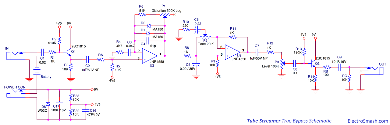
you have an input buffer, built around Q1 , 2SC1815 and in practice almost any NPN small (TO92 case) signal transistor; then the gain/distortion stage, then the active Tone/EQ stage, then a final buffer based on Q3, exactly the same as the first one.
You need just one of these (don't forget the coupling cap) between your guitar and the 25k pot pedal; its output is low enough impedance to not need another.
As a side note, I respect the creativity displayed here by imagining "4558 buffers" , "4558 in parallel" , and so on, but the actual Tube Screamer schematic is easily available all over the Net.

That would make point-to-point soldering much easier, and I could definitely fit it into the 1590LB enclosure. I might try this.you have an input buffer, built around Q1 , 2SC1815:
- Status
- Not open for further replies.
- Home
- Live Sound
- Instruments and Amps
- Multi-stage buffer