Remember that in real world valves the finals start drawing grid current as they approach zero not just as they go positive. that means real world performance of the Cathodyne will be worse than the simulations suggest.
It would be better to use something which has equal drive in all situations.
Shoog
It would be better to use something which has equal drive in all situations.
Shoog
"impedance" is meaningless when a splitter can't swing the required drive currents.
If it can swing both ends properly, then GNF assures artificially low impedances.
Low enough that match is a gimme, and open loop impedance becomes irrelevant.
And then there is blocking distortion... No amount of concertina current or GNF
defeats this evil pumping of the coupling caps. Needs followers, or a deblocker.
Last edited:
Few further thoughts
Although the schematic shows 5965 (12AT7) as phase splitter, the voltages shown are more likely for a 12AU7. (A 12AT7 would be near cut-off with R1 = 1,2K). Looking at anode load graphs for that, the 12AU7 almost goes to zero G1 bias on positive signal cycles, driving a 6L6GC. This can also cause the 'nipple' even without driving a next stage. Operating point would have been better situated with R1 = 1,8K or such. The same will be true for operating a 12AT7 in this mode with only 300V h.t.
This is unfortunately frequently the situation with using a cathodyne with too low h.t. to drive tubes of the EL34/6L6GC/similar ilk. As Shoog said, theoretical Vg = 0V is already quite unsafe. Then with the production spread of tubes these days (as much as 30%), one can run into trouble with having a cathodyne to feed grids at >35Vp signal.
Not wanting to deviate, but I often find that to drive output stages under these conditions (output signal >35Vp), a paraphase topology is better. The input triode must swing full Vpp (G1) anyway, leaving the other triode to deliver only half the signal amplitude of a cathodyne. Yes, there are other inequalities, but of no concern in audio. Just a thought.
Not to nit-pick, but shouldn't R3, R24 be 10K instead of 1K - otherwise the voltages do not equate.
Last edited:
Not sure how you figure that. Are you talking about the schem in post #19? The load line looks like OK to me... The voltages are spot on, bias on the warm side of central, 120Vpk differential swing (twice as much as actually required) before hitting -1V bias. What's not to like?Few further thoughts
Although the schematic shows 5965 (12AT7) as phase splitter, the voltages shown are more likely for a 12AU7. (A 12AT7 would be near cut-off with R1 = 1,2K).
An externally hosted image should be here but it was not working when we last tested it.
Merlinb,
Yes, diagram in post #19. But perhaps I should have started by admitting that some voltages did not read clearly on my screen. I used:
V(C6): +296V
Va: +210V
Vc: +89V
V(R22): +84V
That gives the tube h.t. = 296V, not 390V as your graph shows. Further, I then get about 3,9mA of cathode current to fit all potentials. This gives a tube bias of about 4,6V across R1, which it is.
If I read the above correctly they more or less fit 12AU7 characterisitcs, not 12AT7. The quiescent anode-cathode voltage comes to 125V, not 240V. Taking 40Vp as the maximum signal on the power inputs, this brings the peak low 12AU7 anode swing to about 85V.
Okay - perhaps fine; just .... My tube graphs indicate <-1V on the grid. There is greater amplitude available to the positive anode side, which is why I suggested moving the anode operatoing point somewhat higher.
Last edited:
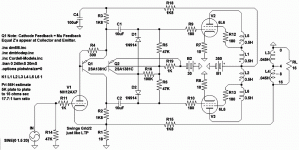
PNP operates fine to less than one collector volt.
Also note:
Equal Z's by attenuated cathode feedback.
Desensitize cathode to act similar to plate.
+/- mu/2 gains at collector and emitter.
Under control of V1, no sand voltage gain.
R4 across VBE provides constant current
to V1's plate, for ideal mu/2 loadlines.
Gargantuan coupling caps and deblocker
to drive grid currents well into AB2.
Attachments
Last edited:
In high feedback tube amplifiers, like some Futterman OTL, the nipple is very big, enourmous, and almost square, due to output saturation and so the entire huge gain loop from input pentode stage is throw to concertina stage, trying in vain control the saturated output. I measured this with scope almost 10 years ago. With O/L (zero feedback) amps, only the fact mentioned at Valve Wizard occurs (aditional gain due to temporary bypassing), so *maybe* high µ tubes will show this effect.
With low feedback amps this will occurs maybe even with low µ tube, if driving hard.
kenpeter,
Interesting the deblocker circuit! I think it's far better than campling/rectifying methods like Carver has used in his last tube amp.
With low feedback amps this will occurs maybe even with low µ tube, if driving hard.
kenpeter,
Interesting the deblocker circuit! I think it's far better than campling/rectifying methods like Carver has used in his last tube amp.
Because Z's were made truly equal, not hiding the deblock of grid in cutoff.
Anything weird that happens at one output grid equally messes with other.
So, my abuse of clamping diodes in the deblocker proves unnecessary.
They could both have been resistors to the same end result.
Would be better if we could pull up the higher grid to mirror the low one.
The drive on the low grid (if we don't mess with it) is true, and reference
that we could watch (the common mode) to correct the positive grid that
is drawing current. Unfortunately, the lower one is easier to pull up.
Followers could deblock better. Then equal z's and big caps are pointless.
Concertina with gains, operating at low tension, perhaps still worthwhile...
Last edited:
Interesting stuff.
kenpeter, I like that circuit, completely new to me. What job does R1 do (18R)?
MelB, $100 a pair for grid chokes is more than I want to spend on this particular amp. I would like to try those chokes, though.
I noticed that you used the 6CG7 with only 3mA per triode. The rp will be well over 10k used like that. Does that make a difference? I thought we want low rp in a cathodyne.
Also, what's the advantage to the paralleled 12AX7 at the input? Perhaps this was a monoblock design, so rather than leaving a triode half flapping in the wind...
DIYBras, this amp will be run without gNFB, if possible. Maybe it'll get -6dB in the end. The schematic is straight from the simulation, so has an unrealistically high value resistor (R20) in series with the feedback resistor, taking it out of circuit. In other words, the amp's running open loop in the schematic. So yes, I'm only seeing that nipple using a high mu triode for the cathodyne, and with no negative feedback around the amp.
My goal here is to get a pair of 6L6-triode output tubes to sound good and make 10W output, and to use as few parts as possible to get there. I want simple, self-adjusting and totally reliable. I found that 6L6-triodes are much more linear running at 360V Vp and 60mA Ip than at the more usual 450V Vp and 45mA Ip. With a grid bias of only -30V, they should be easy enough to drive. EL34-triodes would be better, but I don't have any and they're more expensive than the Russian 6P3S.
I've modeled the circuit with 5965, 6SN7, 5687, EL86-triode and EL84-triode as the phase splitter. According to the models, the two best performing are the 5965 (albeit with that nipple when the 6L6s overload) and the EL84-triode, which looks really, really good (no nipple). Actually, EL84-triode looks like it drives the snot out of the output stage. The problem is that the EL84-triode will pull 20mA per channel from the power supply, while the 5965 draws only 4.5mA per channel. That's a big difference. I might have to compromise and go for 12AU7 or 6SN7, with about 7 or 8mA per channel.
What is the relationship between high-ish rp in the cathodyne and stability when the output stage starts to overload? It seems the lower rp triodes like 5687 or EL84-triode yield symmetrical clipping from the 6L6s, well into overload. Switch to the 5965 or 12AT7 and the nipple appears once the 6L6s overload. I don't think it's a coincidence.
I agree that an LTP with source followers would be better. However, I don't want to mess with a negative supply in this build. Hence the cathodyne, which yields near-perfect balance with few parts and little effort. But I see that the penalty is poor performance once the output stage overloads.
--
Last edited:
Very cool, using lower +B and higher current: this puts the tube more far from bunching/nonlinear low Ia/high Va portion of curves. I tried if with some little triodes like 6EM7 and the effect is the same: lower high-order harmonics, and a better sound.😎Interesting stuff.
kenpeter, I like that circuit, completely new to me. What job does R1 do (18R)?
MelB, $100 a pair for grid chokes is more than I want to spend on this particular amp. I would like to try those chokes, though.
I noticed that you used the 6CG7 with only 3mA per triode. The rp will be well over 10k used like that. Does that make a difference? I thought we want low rp in a cathodyne.
Also, what's the advantage to the paralleled 12AX7 at the input? Perhaps this was a monoblock design, so rather than leaving a triode half flapping in the wind...
DIYBras, this amp will be run without gNFB, if possible. Maybe it'll get -6dB in the end. The schematic is straight from the simulation, so has an unrealistically high value resistor (R20) in series with the feedback resistor, taking it out of circuit. In other words, the amp's running open loop in the schematic. So yes, I'm only seeing that nipple using a high mu triode for the cathodyne, and with no negative feedback around the amp.
My goal here is to get a pair of 6L6-triode output tubes to sound good and make 10W output, and to use as few parts as possible to get there. I want simple, self-adjusting and totally reliable. I found that 6L6-triodes are much more linear running at 360V Vp and 60mA Ip than at the more usual 450V Vp and 45mA Ip. With a grid bias of only -30V, they should be easy enough to drive. EL34-triodes would be better, but I don't have any and they're more expensive than the Russian 6P3S.
I've modeled the circuit with 5965, 6SN7, 5687, EL86-triode and EL84-triode as the phase splitter. According to the models, the two best performing are the 5965 (albeit with that nipple when the 6L6s overload) and the EL84-triode, which looks really, really good (no nipple). Actually, EL84-triode looks like it drives the snot out of the output stage. The problem is that the EL84-triode will pull 20mA per channel from the power supply, while the 5965 draws only 4.5mA per channel. That's a big difference. I might have to compromise and go for 12AU7 or 6SN7, with about 7 or 8mA per channel.
What is the relationship between high-ish rp in the cathodyne and stability when the output stage starts to overload? It seems the lower rp triodes like 5687 or EL84-triode yield symmetrical clipping from the 6L6s, well into overload. Switch to the 5965 or 12AT7 and the nipple appears once the 6L6s overload. I don't think it's a coincidence.
I agree that an LTP with source followers would be better. However, I don't want to mess with a negative supply in this build. Hence the cathodyne, which yields near-perfect balance with few parts and little effort. But I see that the penalty is poor performance once the output stage overloads.
--
For curiosity: some time ago I saw some 807 datasheet (is a different bottle for 6L6), and these datasheet have an multitude of loadlines for pentode and triode modes in it.
About high value grid stopper, I use 10k in my pentode-cathode feedback PL509 output (CFB in Van der Veen terminology), with success. Too high value and HF THD will rise.
Since in overload the output tubes don't "listen" very much to driver tubes (so don't "reproduce" the nipplers in speakers directly), personally I will choice some compromise like 6SN7 family, for example. Of course for less blocking distortion from sustained overdrive (for guitar guys) an version with less cap charge /voltage changing is better (counter example, again: in Futterman OTL 12B4-like version, that super high feedback induced nipple charges the coupling caps a lot and speaker cone bounces like crazy until caps restores the original state).
About high-rp tubes and nipple... well, most high-rp tubes are high-mu, but more investigation is worth it
Last edited:
"..Hence the cathodyne, which yields near-perfect balance with few parts and little effort. But I see that the penalty is poor performance once the output stage overloads."
How about making the splitter clipped before output? 1) cut the extra headroom 2) increase the symmetry so that during clipping the top and bottom clipped at same time. The idea is to maintain the waveform shape the same as much as possible during clipping. After I readjusted the driver bias, the driver and output clipped almost same time and hence leaves no or little room for nipples and therefore the balance. Although in my case the nipple will not affect the output very much as it somewhat buffers by additional drivers stage, it is a good idea the symmetry is always maintained.
How about making the splitter clipped before output? 1) cut the extra headroom 2) increase the symmetry so that during clipping the top and bottom clipped at same time. The idea is to maintain the waveform shape the same as much as possible during clipping. After I readjusted the driver bias, the driver and output clipped almost same time and hence leaves no or little room for nipples and therefore the balance. Although in my case the nipple will not affect the output very much as it somewhat buffers by additional drivers stage, it is a good idea the symmetry is always maintained.
Attachments
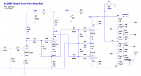
Almost forget... in my experience, the unbypassed R1 results in some little "less-than-ideal" balance behaviour, so is better to bypass them or use fixed bias to grid.Here's a clear screen grab of the schematic. Sorry about the blurry original posting.
Is better to check the resulting THD in normal power levels, maybe is little worse due to tubes go beyond linear range, necessary to saturate before the output. Generally if we make pre stages with plenty of headroom we gain linearity too, but looses in "nipple" situation (is a balance game)"..Hence the cathodyne, which yields near-perfect balance with few parts and little effort. But I see that the penalty is poor performance once the output stage overloads."
How about making the splitter clipped before output? 1) cut the extra headroom 2) increase the symmetry so that during clipping the top and bottom clipped at same time. The idea is to maintain the waveform shape the same as much as possible during clipping. After I readjusted the driver bias, the driver and output clipped almost same time and hence leaves no or little room for nipples and therefore the balance. Although in my case the nipple will not affect the output very much as it somewhat buffers by additional drivers stage, it is a good idea the symmetry is always maintained.
Sorry for the blurry schematic originally posted. Attached is a clearer copy.
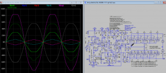
The plate currents for the various tubes are:
12AX7 - 1.04mA
5965 - 3.85mA
6L6 - 60.3mA
Voltages and currents are directly from the LTspice simulation. Reality will differ, I'm sure.
Speaking of reality differing from simulation...
Shoog mentioned that the behavior of the cathodyne will be worse in real life than in the simulation, because the output tubes draw grid current as they approach zero bias (but bias is still slightly negative), not right at zero bias and into positive territory. With that in mind, I think it's better to build in some 'headroom' (as always), and choose a solution that looks silly good in the simulation. That probably means 5687 or EL84-triode.
--
Attachments
Almost forget... in my experience, the unbypassed R1 results in some little "less-than-ideal" balance behaviour, so is better to bypass them or use fixed bias to grid.
I put a 220uF bypass cap across R1 in the simulation, where it made no difference to the overload behavior. In the sim, balance is just about perfect in normal operation, with or without the R1 bypass cap. In real life I would put the cap there and listen, see if I like it better with the cap or without.
Is better to check the resulting THD in normal power levels, maybe is little worse due to tubes go beyond linear range, necessary to saturate before the output. Generally if we make pre stages with plenty of headroom we gain linearity too, but looses in "nipple" situation (is a balance game)
Interesting you should write that. I'm noticing that too. If the sim's distortion predictions are to be believed at all, the choice of tube type for the cathodyne makes a pretty big difference in the THD from the amp. I check the THD and harmonic content at 1W RMS output (2.4V peak into 4 ohms) and at 10W RMS output (7.55V peak into 4 ohms). The reason I'm pursuing this circuit is because the distortion looks really low until 10W out, where it approaches overload. (That's good enough for me in this case.) The lowest distortion is when I use 5965, 12AT7 or EL84-triode. The distortion just about doubles when I use 6SN7 or 5687. The distortion is highest (but still below 0.1% THD at 1W out) when I use 12AU7, 6V6-triode or 12BH7A.
Last edited:
I recently ran across this same problem with some Dynaco MkIII's. They use the triode section of a 6AN8 as a split load PI driving 6550s. I think the real issue is actually a combination of both the lowered impedance of the power tubes near saturation as well as the inability of the PI not having enough drive.
In the case of the Dynacos a 6AN8 that has a triode section that tests 100%+ will have no issue driving both power tubes to clipping symmetrically. <80-90% will cause nipple distortion at the power tube grid like you have and very asymmetrical clipping at the output.
With this in mind I would be inclined to say that the 12AT7 (or it's operating conditions) doesn't have enough drive for this circuit.
Remember that the Dyna MkIII runs 6550 output tubes, which are harder to drive in general, and runs them with a relatively high B+ and low Ia+Ig2, which means they'll be in Class AB1 well before they start to overload. However, they are wired ultralinear, which makes them easier to drive than in triode.
Hmmm... How about paralleled 12AT7? Ia will be 6 to 7 mA, mu is high, ra will be down to about the same as a 6SN7. I'm going to try simulating that...
(Later...) Nope. The nipple still shows up at anything over about 13W RMS output.
Since the ra of two 12AT7 sections in parallel is about the same as that of a single 6SN7 triode, but the nipple doesn't show when using a 6SN7, the appearance of the nipple must be a function of the mu. Low mu is better here, perhaps because when the cathode is unloaded and looks to the anode like the cathode has been bypassed, a high mu triode will deliver a bigger burst of gain than a low mu triode. In this circuit, mu of about 20 seems OK, lower mu seems better. Higher mu raises a nipple (sorry, couldn't resist).
It appears that for lowest distortion under normal conditions, a high mu cathodyne delivers, but the clipping behavior suffers. For best clipping performance, a low mu cathodyne delivers, but distortion will be higher under normal conditions. Whaddya know, another balancing act. Anyone surprised?
--
Last edited:
In the case of the Dynacos a 6AN8 that has a triode section that tests 100%+ will have no issue driving both power tubes to clipping symmetrically. <80-90% will cause nipple distortion at the power tube grid like you have and very asymmetrical clipping at the output.
What was the tube tester testing? Transconductance?
When a tube ages, the transconductance and mu go down, and the plate resistance goes up.
From using a 12AT7 or 5965 as the cathodyne, it looks like higher mu does not help the ability of the cathodyne to drive an overloading output tube's grid.
It would stand to reason that if higher gm was the ingredient for better drive, then high transconductance would help things. But paralleling two 12AT7s (2x gm and 0.5x ra) didn't do anything to reduce the nipple during overload.
Is low plate resistance what's needed, in combination with low mu?
Low mu + low plate resistance + high transconductance = a power tube
That might explain why the EL84-triode looks so good in the cathodyne position.
--
Mutual conductance was tested. You may be onto something with low plate resistance. It's obvious to me that as the 6AN8s age they have less drive. When Hafler designed the MKIII brand new, strong 6AN8s were plentiful and cheap. Now that the stock is 40+ years old it's hard to find good ones.
How does a 12AX7 perform?
Would you be willing to share the .asc spice file?
How does a 12AX7 perform?
Would you be willing to share the .asc spice file?
Last edited:
- Status
- Not open for further replies.
- Home
- Amplifiers
- Tubes / Valves
- 'nipple' in waveform - What is it?