Goodmorning 🙂
I would like to know something about ceramic capacitors - I have a dac pcb in which all the components have been replaced to better more audiophile parts.
There is a 10nF ceramic capacitor located between S/PDIF input and the CS8416 receiver chip!
Since this 10nF is located in the direct digital signal path, I would like to ask all of you about the best capacitor for this solution!
A guy told me install a copperfoil because he claim that it was the absolute best capacitor - But for digital signal transfer, I'm not agree..
Can anyone provide me with a link or something for the best 10nF cap. in this application? 🙂
Best from Vingborg
Last edited:
I would guess the best capacitor is one which is small in size, low in RF losses, and approximately the correct value (which is almost certainly not critical). A 10nF ceramic cap sounds about ideal to me!
You can safely ignore all advice from someone who gives you advice like that. There is no such thing as an absolute best capacitor. In many cases all that is needed is (roughly) the correct value. In some cases the right dielectric should be used. It is almost never the case that special plates are needed - certainly not in audio. High price will improve sound quality for those who know a high price was paid.A guy told me install a copperfoil because he claim that it was the absolute best capacitor
I second AndrewT's recommendation of an C0G/NP0 ceramic dielectric SMD capacitor. S/PDIF signals are in the megahertz range so you want a part with low loss at RF, as DF96 says. C0G/NP0 types feature the most stable dielectric of the ceramic low loss capacitors.
Morning 🙂
Thanks for the answers..
That link AndrewT: That is an smd cap. I need solder pins - Would this capacitor be the same? :
Cap MLCC C0G NP0 10nF 100V Rad Part AVX SR301A103JAA | eBay
Or this? :
Cap MLCC C0G NP0 10nF 50V 0805 Part Multicomp MC0805N103J500A5 08mm | eBay
In this case it would be pretty easy for me to replace this cap 🙂
Vingborg
Buy from an electrical components retailer.
Those prices from Ebay are silly high.
Try Farnell & CPC, RS, Rapid
Those prices from Ebay are silly high.
Try Farnell & CPC, RS, Rapid
Last edited:
Buy from an electrical components retailer.
Those prices frmom Ebay are silly high.
Try Farnell & CPC, RS, Rapid
I'll do that, but are the stuff in the links, the right capacitors? 🙂
Why anybody should use ceramic, when stacked film SMT caps are available?
Anyway, 10nf is few orders of magnitude too small, you need good HF and LF performance, from few Hz to few tens of MHz.
Anyway, 10nf is few orders of magnitude too small, you need good HF and LF performance, from few Hz to few tens of MHz.
Because COG/NP0 are excellent capacitors that's why, look them up, used for HF especially RF all the time, and here low RF loss is desirable!
Again generic classification of ceramic capacitors!
Why do you need low frequency performance for SPDIF signals?
Again generic classification of ceramic capacitors!
Why do you need low frequency performance for SPDIF signals?
In that position a 10nF silver-mica will be best, seconded by a 10nF C0G/NP0. Polystyrene can also perform excellent at ~ 3MHz (2.8224 Mbit/s for 44.1K sampling).
http://uk.farnell.com/cornell-dubilier/cd30fd103jo3f/silver-mica-capacitor-0-01uf-500v/dp/1341740
http://uk.farnell.com/cornell-dubilier/cd30fd103jo3f/silver-mica-capacitor-0-01uf-500v/dp/1341740
Regards,
Tibi
http://uk.farnell.com/cornell-dubilier/cd30fd103jo3f/silver-mica-capacitor-0-01uf-500v/dp/1341740
http://uk.farnell.com/cornell-dubilier/cd30fd103jo3f/silver-mica-capacitor-0-01uf-500v/dp/1341740
Regards,
Tibi
Last edited by a moderator:
marce said:Why do you need low frequency performance for SPDIF signals?
Aren't you expert for digital, always giving others examples and links to dr. Howard Johnson's web page? How about signal integrity?
With too small coupling cap, you will get LF tilt and altering waveform of signal. LF tilt will affect edges of signal and moving decision point.
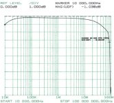
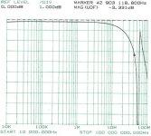
DF96 said:SPDIF can get through quite a small transformer, so it can't have much low frequencies in it.
Working and working good are two different things 😀
Of course, there is no free lunch and any designer must decide what is more important, limited BW or galvanic isolation.
BW measurements for Newava 22083 and PE-65612 are courtesy from Jocko Homo
Attachments
Last edited:
Goodmorning 🙂
Thanks for all the answers - It seems to me like 10nF could be too small a value, when I reed this post from Stormsonic.. Or am I wrong?
Well, I purchased 2 pcs. of this one: Cap MLCC C0G NP0 10nF 50V 0805 Part Multicomp MC0805N103J500A5 08mm | eBay
I could bypass both so the value will be 20nF!!
Would it be an advance? Would it hurt something?
Can anybody clarify that?
Best from Vingborg🙂
Aren't you expert for digital, always giving others examples and links to dr. Howard Johnson's web page? How about signal integrity?
With too small coupling cap, you will get LF tilt and altering waveform of signal. LF tilt will affect edges of signal and moving decision point.
Working and working good are two different things 😀
Of course, there is no free lunch and any designer must decide what is more important, limited BW or galvanic isolation.
BW measurements for Newava 22083 and PE-65612 are courtesy from Jocko Homo
Thanks for all the answers - It seems to me like 10nF could be too small a value, when I reed this post from Stormsonic.. Or am I wrong?
Well, I purchased 2 pcs. of this one: Cap MLCC C0G NP0 10nF 50V 0805 Part Multicomp MC0805N103J500A5 08mm | eBay
I could bypass both so the value will be 20nF!!
Would it be an advance? Would it hurt something?
Can anybody clarify that?
Best from Vingborg🙂
Paralleling two identical caps in a situation where the value is noncritical should be fine. Unnecessary, but should do no harm.
Data sheet for receiver chip, info on page 49/50...
http://www.mouser.com/ds/2/76/CS8416_F3-34501.pdf
Some more info on the interface would be helpful, is there a 75R resistor?
Do you think that swapping what is already their for an audiophile component is going to improve things?
http://www.mouser.com/ds/2/76/CS8416_F3-34501.pdf
Some more info on the interface would be helpful, is there a 75R resistor?
Do you think that swapping what is already their for an audiophile component is going to improve things?
The manufacturer is happy with 10nF as the input coupling cap. Did he misunderstand his own chip design?
Ah but that's not the audiophile way...
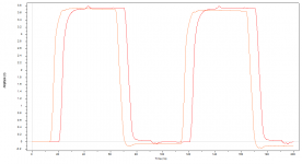
As to signal integrity maybe some should study it more, there does seem to be a view that SI equates to the steepest wave edges! even rounding the wave of does not matter that much, as long as the switching intervals are constant (minimum jitter) then it don't really matter..... in fact reducing the HF content can be benefitial...
As to WHY you need a cap from a few Hz for digital is beyond me, the base frequency will be around 3MHz so you don't need anything below that...
A quick sim, SPDIF with cap (orange) without cap (red) just added it to the sim I did last year! or earlier for another SPDIF thread...
Attachments
Data sheet for receiver chip, info on page 49/50...
http://www.mouser.com/ds/2/76/CS8416_F3-34501.pdf
Some more info on the interface would be helpful, is there a 75R resistor?
Do you think that swapping what is already their for an audiophile component is going to improve things?
Hello🙂
The S/Pdif input have a 75ohm resistor straight to ground before the 10nF cap and then into the 8416 receiver chip.
The reason for all this is that a friend of mine have a cheap china pcb with a CS4398 dac chip. He have modified this pcb pretty much, and through his tube output stage, the sound is amazing. I have provided myself with the same pcb and done the same regarding the components.. The last piece I need is this small 10nF cap!
Some might say that it dosen't make any difference, and that maybe true, but in the spirit of diy and high quality reproduction of sound this cap has to be replaced just to be faithful to this heavily tweaked dac pcb!
I don't know much about digital signals.. I'm much stronger with tube output stages😉 That's why I'm asking to this very small cap direct in the digital signal path.
The pcb is born with a 10nF cap and that is what I'm about to put in, but if somebody tells me to install a bigger/smaller different type, then I'm open for suggestions! The price for one or two pcs. is only a few pennys I believe🙂
Vingborg🙂
- Status
- Not open for further replies.
- Home
- Source & Line
- Digital Source
- Ceramic capacitor for digital signal transfer