Well, perhaps I was over-enthusiastic with the analysis and scope work. 🙂As a side note, what output problem? Looks fine to me.
It does sound a bit overly distorted to me - perhaps a master volume would control that overdriven aspect a bit better.
I would retest but doubling and halving load impedance, one will be "better" (at least more symmetrical and you might clip power tube grid) , the other will be the opposite.
Try all 3 and post results.
OK- will do...I'm assuming you mean to just swap in different dummy load resistances?
Back in a few minutes.....
Thanks for that suggestion!I would retest but doubling and halving load impedance, one will be "better" (at least more symmetrical and you might clip power tube grid) , the other will be the opposite.
Try all 3 and post results.
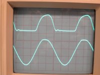
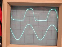
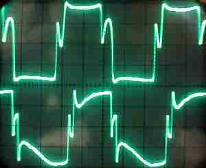
Yes, you were absolutely correct - the clipping is more symmetrical with higher impedance load.
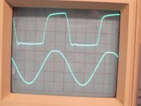
Attached pics show patterns with 4,8,16 ohm dummy load. Output at load is top trace, grid of power tube is bottom trace.
Perhaps this is why the (scope) results with a speaker attached didn't show the same sort of patterns - due to the changing speaker impedance with frequency?
So perhaps I shouldn't worry too much about this, and look at overdrive and levels throughout the amp if I think there's too much distorted sound?
Attachments
So perhaps I shouldn't worry too much about this, and look at overdrive and levels throughout the amp if I think there's too much distorted sound?
Yep. That is where I was pointing you in my first post. Your understanding is better if you can get there on your own self.
And my understanding is better when I try and help others.
Cheers
JimG
PS. The scope traces were a big help in understanding your question
Last edited:
Yes, with a complex load such as a speaker the waveform gets even kinkier.Thanks for that suggestion!
Yes, you were absolutely correct - the clipping is more symmetrical with higher impedance load.
Attached pics show patterns with 4,8,16 ohm dummy load. Output at load is top trace, grid of power tube is bottom trace.
Perhaps this is why the (scope) results with a speaker attached didn't show the same sort of patterns - due to the changing speaker impedance with frequency?
Basically yes.So perhaps I shouldn't worry too much about this, and look at overdrive and levels throughout the amp if I think there's too much distorted sound?
It's a guitar amp and you are presumably playing some variant of Rock (that includes Blues, etc.) so distortion is a given.
And your waveforms are normal for anybody who *actually* uses his Scope to know what's going on.
I am *appalled* by the tons of misinformation which gets copied and pasted all over the Internet without analysis orverification.
If you search for guitar amp distortion, 99% of the time you will be offered some variant of the following, namely "tube amps clip rounded, SS amps clip squarewave ...." and an accompanying graph similar to one of these:

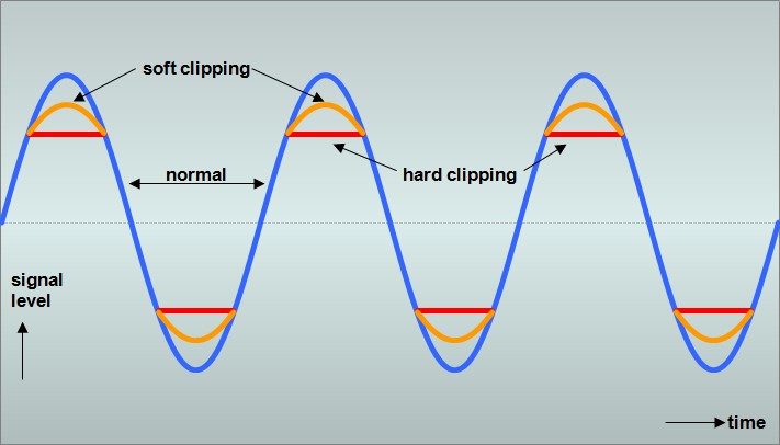
truckload of bull manure !!!!!!!!!!
Notice that these are *drawn* graphs, never a scope screen is offered as proof.
And coming from BIG manufacturers (won't give names 🙄) .
truth is this, in this case an overdriven Marshall 18W`(killer little amp) which is anything but "polite" 😀 :
More symmetrical than yours simply because it's a push pull amp , so imagine you take your single ended waveform, photocopy it on transparent paper twice, put one of them upside down on the other and draw what you get.
And even so it's not that symmetrical 😉 , for 2 very good reasons:
1) both tubes are not perfectly matched .
You can match *bias* or idle current, but even so real world tubes will have different gain/transconductance/emission/etc.
2) even if you did, regular PI do not provide perfectly symmetrical outputs anyway.
Using different plate resistors (often 82k/100k) is a way to minimize this, but even so ......
And both halves of the PI are also different, even if inside the same bottle.
The bottom end is that it sounds good, even if it looks ugly.
JM I think the real waveform looks beautiful, much more interesting than a clipped sine. If you plug a spectrum analyzer at the output it is very nice as well lots of interesting spectra in real time.. ;-)
Yes 🙂 , that's my point.JM I think the real waveform looks beautiful, much more interesting than a clipped sine. If you plug a spectrum analyzer at the output it is very nice as well lots of interesting spectra in real time.. ;-)
I can't believe how much the wrong explanation is passed around and still alive, I mean all those guys (at least the Factories) must have scopes 🙄
User Loudthud (I think he posts in DYA too) has tested and posted lots of Tube Amp scope pictures, showing everything that goes on, real world.
Literally, eye opening.
Yeah, they must have scopes, right?. But maybe more comfortable with just perpetuating myths based on some commonly held (mis-)beliefs.
VictoriaGuy is going about it the right way though, looking at the waveform , questioning measured results against what the common expectations are. It is the way we should learn. Theory and practical lab. Good stuff!
VictoriaGuy is going about it the right way though, looking at the waveform , questioning measured results against what the common expectations are. It is the way we should learn. Theory and practical lab. Good stuff!
Man, I'm glad I ran into this thread! I'm playing with a preamp based on the Marshall 18W, and use my scope all the time. This thread will probably answer many of the questions I will have. Thanks all!
Looking at the scope screenshots it is obvious that the clipping coincides with neg halfwaves at the grid. In other words - the clipping is synchroneous to the tube totally blocking. Nothing to wonder about.😉
Edit: just discovered the posting auf Juan - which I totally agree.
Edit: just discovered the posting auf Juan - which I totally agree.
Last edited:
On your schematic the 10MOhm resistor above the volume pot wiper is in the Wrong place.
It should be directly across the bright switch such that it is shorted out when you switch to bright. Its just to prevent pops when switching the bright switch on and off.
Cheers,
Ian
It should be directly across the bright switch such that it is shorted out when you switch to bright. Its just to prevent pops when switching the bright switch on and off.
Cheers,
Ian
Thanks, Ian. It's not 'my' schematic, but I know what you mean. Actually, on the hand-drawn schematics, one has the resistor across the switch - but that one is missing the bright cap.On your schematic the 10MOhm resistor above the volume pot wiper is in the Wrong place.
It should be directly across the bright switch such that it is shorted out when you switch to bright. Its just to prevent pops when switching the bright switch on and off.
Cheers,
Ian
I left the 10M out of my build, so not a problem for me!
I didn't expect a pop problem on that switch (no DC on it, which is usually where I hear problems), and didn't get any pop.
- Status
- Not open for further replies.
- Home
- Live Sound
- Instruments and Amps
- Scope distortion pattern- diagnose problem?