IRS2092 class d amps can be a minefield for beginners.
It took me 3 pcb revisions to get one that didn't keep on resetting at high powers.
Decoupling close to 2092 and mosfets is vital.
Close pcb layout is vital.
On a 2000 watts design I used 22,000uF electrolytics on each supply rail.
On power off I would get a loud siren noise and after a few seconds a huge thump through the speaker.
I got in touch with IR and they said the 2092 doesn't like slowly discharging power supplies and suggested a reset circuit. So I added small PIC micro to monitor VCC and if it fell too low it held the 2092 in reset through an opto coupler. Worked a treat.
I never really got to the bottom of false resets but I found I had to keep the OC components set to high voltages.
I had a long saga with suitable mosfets for the 2092. In the end I found to get high power I had to use multiple IRFB4227's with transistor gate drivers capable of 6 amps.
The 2092 likes mosfets to switch on fast, if they don't it thinks there is a over current event and resets itself.
IRS2092 class d amps can be a minefield for beginners.
It took me 3 pcb revisions to get one that didn't keep on resetting at high powers.
Decoupling close to 2092 and mosfets is vital.
Close pcb layout is vital.
On a 2000 watts design I used 22,000uF electrolytics on each supply rail.
On power off I would get a loud siren noise and after a few seconds a huge thump through the speaker.
I got in touch with IR and they said the 2092 doesn't like slowly discharging power supplies and suggested a reset circuit. So I added small PIC micro to monitor VCC and if it fell too low it held the 2092 in reset through an opto coupler. Worked a treat.
I never really got to the bottom of false resets but I found I had to keep the OC components set to high voltages.
I had a long saga with suitable mosfets for the 2092. In the end I found to get high power I had to use multiple IRFB4227's with transistor gate drivers capable of 6 amps.
The 2092 likes mosfets to switch on fast, if they don't it thinks there is a over current event and resets itself.
thanks for sharing your experience , as stated by you , i have done all the above mentioned , and for the turn of sound i have attached a relay that is operated by a AC sense circuit , as soon as the mains is turned of the relay switches of , there by removing and noise .
regards
and the basic specs of the Class- D is as follows.Glad to see a design contribution again.
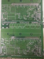
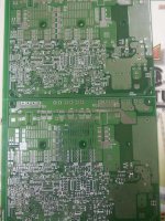
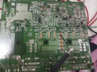
A first view to your PCB looks like you have spend some thoughts on keeping low the inductances of the most crucial loops - keeping fingers crossed.
Components:
- The picture of your older version shows the output filter choke with dual or
triple layer winding. Single layer is definitely preferable in terms of parasitic winding capacitance.
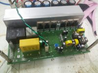
- You should have a look to the AC current stress of C90 and C92.
It is hard to judge without knowing your switching frequency + rail voltages + inductance of the output choke ... but seeing the target power and load impedance, it is likely that already the current ripple during idle is critical for average e-caps.
1. Switching freq = 380Khz
2. Intended Supply Range = +- 70-95VDC
3. O/p Inductor = 22uH
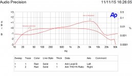
some measurments that i did
Power = 500W@4E
SNR = 102dB
Thd at full power = 0.6%
Thd at -3db = 0.017%
Supply voltage = +-70VDC
Frequency Response = 10Hz- 30Khz
Power = 500W@4E
SNR = 102dB
Thd at full power = 0.6%
Thd at -3db = 0.017%
Supply voltage = +-70VDC
Frequency Response = 10Hz- 30Khz
Hello,
What type of class D is this amp ?
Did you simulated it before building it ? If so with which simulator ?
Finally, which company manufactured your PCBs ?
What type of class D is this amp ?
Did you simulated it before building it ? If so with which simulator ?
Finally, which company manufactured your PCBs ?
this is a self oscillating class-d amp based on the application note from IRF(IRAUDAMP9), no i didnt simulate it ,
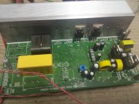
Completed assembling the power stage , and pulled 800W @ 4E , the amp seemed quite happy doing that. Uploading pics of the assembled amp top and bottom side. currently trying to set the OCP levels.
regards
Completed assembling the power stage , and pulled 800W @ 4E , the amp seemed quite happy doing that. Uploading pics of the assembled amp top and bottom side. currently trying to set the OCP levels.
regards
Attachments
- Status
- Not open for further replies.
- Home
- Amplifiers
- Class D
- 1200W @ 2E WITH IRS2092