I've just recently dove down the rabbit hole that is headphone listening and at the same time recently purchased my first DAC. A rather well-known company that I bought my little DAC from has an amp that uses a sub-mini pentode in triode-strapped feeding into a solid output that (from what I've heard) is quite the package.
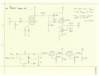
I also just recently completed a cathode-follower with active load (ah-la broskie design) that sounds very pleasant as a driver. As nice as it sounds, its quite large and the sub-mini / sand route seemed interesting so I thought I'd give it a whirl. Jut ordered some additional oddball parts that I didn't have laying around to start experimenting with this. Attached is the "rev1" persay and I'll go from there.
I'm planning on using the 6088 Raytheon but I put the note in there that I'd like to try the 12W6 as well, as I've heard them likened to a 45 in sound when triode strapped. Thought it could be fun. The one drawback to using the 12W6 is that I'd like to get up around the 200V Vp range so I'd no longer be able to use a wall-wart and probably pick up a torrodial with a higher output and re-design the PSU a bit.
As you can see, there's no volume pot included as I was planning on controlling volume with the software when I doddled this up. That's going to change and I'll be including one in there eventually. I was originally going for simplicity but having a stronger signal will give me a better SNR *doh* so I'll include it.
Hopefully will be getting everything early next week and I'll start putting everything together then! In the meantime...discuss. Also, gets its name as this is a hybrid SPUD amp 😛
Attachments
Last edited:
Actually no, not to my knowledge anyway (so chances are its a legitimate mistake!). I'm having to do a bit of looking yet on the whole mosfet bias thing (so bear with me) but afaik, you're going to need some way to set the Vgs/Vds bias. The way I've got it drawn, is a fixed Vg through a voltage divider and you've got it biased with a drain-gate feedback resistor. I guess most of the simple circuits I came across used a fixed bias topology over the feedback resistor but I've also not done NEARLY as much looking into SS stages yet either 😛
Last edited:
For a follower, the exact bias point isn't very important. I would just use 100k to B+2 and 100k to ground. It will bias up with the source about 4V below B+2/2.
If you were trying to eliminate the output coupling caps, then it becomes important, but you would need a bias servo to be safe. Otherwise drift will put a bit of DC at the output.
Any number of triodes will work at ~50-75V (contrary to what most people will tell you 😉 ) . The 6DJ8/6922/ECC88 is very linear there, and the 6SN7 does well too.
Pete
Member
Joined 2009
Paid Member
Looks interesting!
If you derive the B2 supply from B1 will you be wasting a lot of power ? perhaps a separate supply is worth it.
FETs often need a diode somewhere to protect the gate from swinging outside of its safe range.
If you derive the B2 supply from B1 will you be wasting a lot of power ? perhaps a separate supply is worth it.
FETs often need a diode somewhere to protect the gate from swinging outside of its safe range.
For a follower, the exact bias point isn't very important. I would just use 100k to B+2 and 100k to ground. It will bias up with the source about 4V below B+2/2.
If you were trying to eliminate the output coupling caps, then it becomes important, but you would need a bias servo to be safe. Otherwise drift will put a bit of DC at the output.
Any number of triodes will work at ~50-75V (contrary to what most people will tell you 😉 ) . The 6DJ8/6922/ECC88 is very linear there, and the 6SN7 does well too.
Pete
Good to know. I've got a BUNCH of other triodes i could put in there as well, I've just been real interested with the 12W6. I *think* if I did run it down there it *could* be okay, still allowing a 3V p-p but I'd like a bit more. Could use a 12B4A as well looking just now.
Looks interesting!
If you derive the B2 supply from B1 will you be wasting a lot of power ? perhaps a separate supply is worth it.
FETs often need a diode somewhere to protect the gate from swinging outside of its safe range.
I was wondering about that as well, I could always just pull the 2nd regulator from between the two caps for a 30V potential to regulate down. Coming to think of it, that might be a better option anyway as I'll have less drop-out. Both of those regulators will have heat-sinks but I think I might do that now. Also I had put the LM350 in there for its higher current capability but splitting out that voltage will let me just use LM317HV's everywhere. Simplification. I dig it!
Also from what i can see the IRF610 has a max Vgs of +/-20V so I think I'll be alright. I guess if the LDO did fail close and give it 60V there could be a chance to push over that but typically I've seen them fail open. It wouldn't hurt to put a 15V Vgs zener in there though 😉
Last edited:
Also since none of you jokers have posted it yet, here's a pomato:

I do quite like both cherry tomatoes and 'taters. 😀
I do quite like both cherry tomatoes and 'taters. 😀
Well, at least it's healthier than:
An externally hosted image should be here but it was not working when we last tested it.
Layout
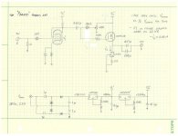
Had a quick break over work today and did a little work on the layout. I'm thinking the output jack and the volume knob will be sticking up vertical and I'll run the left/right channel underneath to the rear and have those jacks sticking out the back.
Couple changes on scheme, got rid of the bias pot per suggestion and also added a second coupling cap due to the addition of a volume pot. Placement of the IRF610's and the LM317's will be such to toss a heat sink on if necessary. Probably will be laying the 6088's towards the rear. Might do a cutout or something on the case so you can see them plus aleviate any packaging issues that might cause with the output jack and vol pot.
Attachments
Last edited:
You might want to change the 100K to the FET gate bias and keep it at least 5 and preferably 10 times the value of Rp as shown on your drawing. This will help keep distortion down.
Quick update. Got some stuff wrapped up for both my broski amp and a few more parts for the pomato. Waiting for my AC wall wart for the voltage supply for the pomato yet but couldn't wait to get some parts on the board.
Top is the broski amp that I'm point-to-point wiring in an old cashbox that i picked up. Bottom is the beginning for the pomato.

Top is the broski amp that I'm point-to-point wiring in an old cashbox that i picked up. Bottom is the beginning for the pomato.
Holy heck....life does get busy doesn't it?
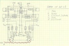
Finally wrapping up on the big broskie design and monday I ordered some of the last parts for the pomato (wall wart, power receptacle....etc). I've been kind of racking my brain to figure out how to supply the heaters with these guys lately. These will be the venture for me into DHT's and in some looking I've found that its pretty common for y'all to use a filament supply of some flavor. Has me curious now if that's something I need to be looking into more. What I've come up with as of now is using a 350/317 as a current regulator into a 10Ohm to give me the 1.2V required for the filament. Looking at this after uploading it, I noticed that I neglected the 40mA combined from the two tubes, so the regulator would have to be set to 160mA or so to keep the correct voltage and current supply to the filaments. No idea if this is a viable option or not, wondering if anyone can weight in on that.
Additionally as noted earlier in the thread I was silly for wanting to stack the LDO's for my two regulators. Below is a bit more reasonable approach.
- Status
- Not open for further replies.
- Home
- Amplifiers
- Tubes / Valves
- The Pomato, A hybrid can amp