I'm just finishing a P2P build of Rob Robinette's 'Bassman Micro' amp - a low-power guitar amp based on the Fender Bassman 5F6A, which uses the triode sections of a 12AU7 in push-pull as the power section.
Here's the link to Rob's webpage with the schematic and build details:
https://robrobinette.com/Bassman_Micro.htm
Schematic:
https://robrobinette.com/images/Guitar/Bassman_Micro/Bassman_Micro_Schematic.pdf
I've run into a problem with buzzing - especially noticeable in the bass frequencies, and I'd appreciate hints on how to proceed..
Here's a link to a video showing what it looks like on the 'scope.
100Hz sine wave input @100mV
Scope on speaker leads.
https://youtu.be/TKv1Nzph6Z4
Raising the volume with either the (input) volume or the master volume causes a buzz which starts as a 'bip-bip-bip' and increases to a buzz as the volume is advanced.
I'm pretty sure it's not a tube problem, as I've swapped in a couple of different sets of tubes.
DC Voltages seem 'normal-looking' to me:
B+ is around 280V
Plates of the output 12AU7 are at 275V
Cathode to ground voltages on output tube 9.5V
Ideas, please! Thanks!
Attachments
It looks like some sort of parasitic oscillation. It doesn't look to me like positive feedback, though a test is simple. Does switching the negative feedback switch change it at all? If you can just disconnect the NFB, does that stop it?
Otherwise, I'd scope the B+ in the preamp and see if it is riding the supply.
Otherwise, I'd scope the B+ in the preamp and see if it is riding the supply.
It looks like some sort of parasitic oscillation. It doesn't look to me like positive feedback, though a test is simple. Does switching the negative feedback switch change it at all? If you can just disconnect the NFB, does that stop it?
Otherwise, I'd scope the B+ in the preamp and see if it is riding the supply.
Thanks, Enzo.
I don't think it is positive feedback - when I first wired it up, I had to reverse the OT primary leads because it was positively feeding back via the NFB circuit.
Now, switching the NFB (it's an ON-OFF-ON switch so the middle position disconnects the NFB) makes no difference to the onset of the buzz.
I don't know what 'riding the supply' means, sorry. Scoping the B+ means looking at the AC on the B+ supply?
BTW, I've added another RC filtering stage to the PS now as lack of decoupling between stages was something mentioned online as a possible cause of motorboating. So now there's B+1, B+2, B+3 supply, but it made no difference.
I also reduced the final coupling caps from 0.1 to 0.03uF, but no effect from that either.
With the input shorted, the amp is completely silent. This buzz is only on bass notes (bottom octave of guitar).
B+ should be smooth DC, with maybe a trace of 120Hz ripple. By riding, I meant see if that spurious oscillation signal was impressed on the B+. Scope the B+ and see if the noise signal appears there. if you have added multiple decouplers, this is probably not the failure mode.
So shorting the input results in silence, and the noise only appears on peaks anyway. So that is sorta expected.
try injecting your 100Hz into the master volume, thus driving only the PA. Does this still happen? Or inject at the other volume control, bypassing the first stage, still happen?
I might suspect lead dress. A large signal at the output stage is coupling back into an earlier stage. With a steady input at a level to make the symptom steady, push all the wires around with a wooden stick to see if moving any affects it in any way. Worry particularly with grid wires.
Pull the output tube V3, is the noise still present at the phase inverter?
The whole point of the exercise is to isolate the problem. How many stages are involved, and if it is a loop of some sort, how many stages does it include.
sounds like a diode going into breakdown. are you SS or tube in the rectifier section?
even with tube rect if you have the backup diodes shown in the schematic that's likely the source.
even with tube rect if you have the backup diodes shown in the schematic that's likely the source.
The schematic shows the first pre-amp stage and the PI stage as two halves of the same double triode (V1A and V1B). That seems a bit unusual. I believe the internal capacitance between the plates of V1A and V1B will only be around 1pF, but could the proximity of the wiring of these two triodes be a causing a parasitic problem? Maybe some 'chop sticking' of the wiring there could be worth a try.
Thanks for the hints and advice; I appreciate it. I'll get back at that amp later today and report what I find.
More info:
The power supply uses ss diodes, not a tube rectifier. All the components are/were 'new'/unused from my parts box here, except for the transformers. Still, bad parts are a possibility, I suppose.
The wiring is point-to-point using the components to make the connections where possible (not eyelet board with longer wires to the tubes and controls), so the possibilities for moving wires are limited. I have pushed wires around with a chopstick to no effect.
I did wonder about sharing V1 between the first preamp stage and the PI, and I may have made the situation worse by making all those connections as short as possible.
I'll post a pic or two later.
Thanks again for the help!
Some pics:
Attachments
-
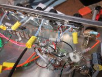 V1 V2 and controls.JPG173.9 KB · Views: 201
 -
 V1 V2 with switched V1 cathode bypass.JPG151.8 KB · Views: 196
 -
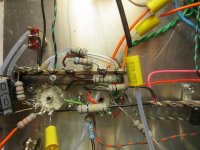
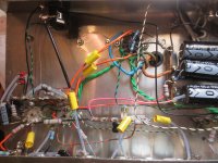
 V3 power PP triodes 12AU7.JPG117.8 KB · Views: 193
 -
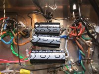 power supply section diodes under.JPG165.8 KB · Views: 200
 -
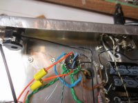
 leads to back panel for Pre out and NFB connection at speaker jack.JPG175.7 KB · Views: 200
It's a bit difficult to make out in the photos, but it looks like your PI is grounded to the same point as the first pre-amp stage. I can't make out enough to see what your grounding scheme is. But I would think that grounding the PI to the point where the master volume is grounded, and grounding the first pre-amp stage to the point where the input jack is grounded should be better. (Just take this as a possible suggestion! I can't make out how the grounding is laid out well enough to be sure.)
Last edited:
Two eyelet board Bassman Micro's have been built with no problems but this is the first true point-to-point Bassman.
I watched your video VictoriaGuy and I see the buzz is coming right at the peaks of amplification so it appears to be being created in the gain stages themselves.
Scope the first gain stage at the the V1A grid pin 2 and see if the buzz is present there.
Then scope V2A pin 2 (second preamp), then V1B pin 7 (phase inverter grid), then V3A & B's grids pins 2 & 7 (power tube grids) to find the source.
I did a few 'diagnostics'.
First, injecting signal at the input jack, and scoping different points (with the buzz evident at the speaker):
V1 Pin 2 (1st pre grid) normal trace
V2 Pin 2 (2nd pre grid) normal trace
V1 Pin 7 (PI grid) normal trace
V3 Pins 2, 7 (Power tube grids) distorted waveform
Next, injecting signal at different points (adjusting audio generator to give the same volume/buzz at speaker):
Inject at input jack Buzz
Inject at V1 Pin2 (1st pre grid) Buzz
Inject at V2 Pin2 (2nd pre grid) Buzz
Inject at Master Vol (just before coupling cap to preamp out and PI) Buzz
Inject at V1 Pin7 (PI grid) Buzz
Inject directly to power tube (V3) grids - no buzz (at max output from audio generator).
So it looks like the problem is 'later' in the signal chain?
Grounding:
All the jacks (input,preamp out, and speaker) are isolated from the chassis.
Grounds lead back to the chassis point where the PT HV CT and the AC line ground are attached.
Heater ground (artificial CT with 2 x 100ohm resistors) is tied to the power tube cathode.
This is the first guitar amp build where I've tried a buss along the front panel controls (heavy wire connected to the input jack and control grounds, with a wire connecting the buss to the ). I realize this wasn't a good choice for this amp with the Volume and Master volume adjacent, etc. .
So I'm going to rearrange things to make the grounding a bit better, eliminating that buss wire and following Malcolm's suggestions. I'll report back. Even if it doesn't cure the buzzing problem, it will match my usual style of building.
BTW, in the pics the ground wires are the black ones.
Thanks again for the suggestions - I usually don't 'go public' with my mistakes/problems, but hopefully this may help somebody else.
In the previous post, I forgot to mention that the B+ looks clean and doesn't show the buzz - i.e. when the buzzing starts (as I advance the volume/MV controls) the very small amount of ripple on the B+ doesn't change on the scope.
I re-arranged the grounds into a 'galactic ground' style - collected the grounds from the different sections and tied them back to the ground point separately.
It didn't make any difference to the buzzing issue.
Could this be an output transformer issue? I can't remember how that OT ended up on my shelf, but at some point I'd labelled it with the impedance ratio. I have a new OT which should arrive in a couple of weeks. I may look on the shelf to see if I have an OT that can 'get close' by picking the right secondary tap for the 8ohm speaker.
In the meantime, I may breadboard a different power amp section and connect that to the preamp out of the Bassman micro (though I'd rather get this circuit working, since it has been built successfully on eyelet board).
Last edited:
Is that mile long capacitor with the black sleeve on the wire lead going to the input jack? Try shielding that thing. Of for science, remove it and tack a cap to the tube scket or wherever it goes, without the long leads, and inject a signal directly into it. See if getting rid of the very long lead wires on an input helps. Perhaps a shielded lead there?
Is that mile long capacitor with the black sleeve on the wire lead going to the input jack? Try shielding that thing. Of for science, remove it and tack a cap to the tube scket or wherever it goes, without the long leads, and inject a signal directly into it. See if getting rid of the very long lead wires on an input helps. Perhaps a shielded lead there?
Enzo-
I should have tried to label the pictures - sorry for any confusion.
No, that cap is the coupling cap after the master volume which is connected to the preamp out jack on the back panel, not the input.
but I'll take a minute and eliminate that preamp out for now.....
back soon....
From your experimenting it appears the phase inverter circuit is creating the buzz. Please post all pin voltages of the phase inverter (V1 pins 6, 7 & 8), inspect the circuit very closely--make sure it matches the schematic and measure the component values, especially the resistors. Something is screwy there.

Rob:From your experimenting it appears the phase inverter circuit is creating the buzz. Please post all pin voltages of the phase inverter (V1 pins 6, 7 & 8), inspect the circuit very closely--make sure it matches the schematic and measure the component values, especially the resistors. Something is screwy there.
Thanks for those suggestions.
I re-checked the PI wiring (twice) against the schematic and it looks OK.
Re-checked the markings on the resistors, and also checked them with an ohmmeter and they are correct - as in schematic. 1M,270k, 1k5, and 56k
However, the Pin 7 V1 grid (PI) voltage is not the same as you found, according to the web page. You found 4v on the grid; I get 30v with two different 12AY7 tubes, 17v with two different 12AX7 tubes in that V1 socket.
Pin6 (plate) voltage is 208, Pin8 (cathode) voltage is 74v- those match your values.
I disconnected the coupling cap from the MV (to eliminate a DC leaky cap as the cause of the higher voltage on the grid) and it made no difference - 30 volts.
The voltages listed on the Bassman Micro webpage are quiescent (no signal) but 4v on the phase inverter grid seems to be off, possibly a typo. Your 30v for a 12AY7 and 17v with a 12AX7 looks to be about what's expected in a cathodyne circuit.
Maybe your layout is causing the problem.
Maybe your layout is causing the problem.
4v on the PI grid is totally wrong. The problem is you usually cannot reliably measure the grid voltage with a meter to ground. Your meter impedance and the 1M grid resistor form a voltage divider, so the voltage looks about half what it ought to. 4v means about 70v of negative bias, which would cut the tube off.
The bias is created by the 1.5k resistor at the cathode, just like the input stage. Note the grid return resistor connects to the bottom of the 1.5k, and that voltage is applied to the grid through the 1M. The way to measure the voltage on that grid is to measure the voltage across the 1.5k. If you measure the voltage from cathode to grid, rather than grid to ground, you will get an accurate reading. The grid will be a couple volts less positive than the cathode, so measure the cathode voltage, and subtract the couple volts from it for the real voltage. But what matters is that couple of volts.
The bias is created by the 1.5k resistor at the cathode, just like the input stage. Note the grid return resistor connects to the bottom of the 1.5k, and that voltage is applied to the grid through the 1M. The way to measure the voltage on that grid is to measure the voltage across the 1.5k. If you measure the voltage from cathode to grid, rather than grid to ground, you will get an accurate reading. The grid will be a couple volts less positive than the cathode, so measure the cathode voltage, and subtract the couple volts from it for the real voltage. But what matters is that couple of volts.
I did some reading on cathodyne PI circuits at
The Valve Wizard
and added grid stoppers (100k) to the power tube grids.
Problem solved - no more nasty buzzing or blips on the scope trace.
I increased the value of the grid (leak) resistors as well (as I was concerned that the grid stoppers were just acting as a voltage divider to decrease the input to the power tube grids).
Last edited:
- Status
- Not open for further replies.
- Home
- Live Sound
- Instruments and Amps
- Problem with 'Bassman Micro' 5F6A build -Help!