Any idea who at Bryston came up with the triple-compound idea ?
(James, some ketchup for my Frank-footer please)
(James, some ketchup for my Frank-footer please)
I think you need to experience driving a Bentley rather than judge by its looks. .......................
THx-RNMarsh
..................next you'll be offering JC a ride and marketing mystical thingmajigs, derived from the Defence Industry, which improve the sound of any sound system....provided it is not going on sale in the Eastern Bloc!
Just leg-pulling!
😀😀😀😀
Last edited:
I'd guess the founding father himself, but I don't know.Any idea who at Bryston came up with the triple-compound idea ?
You are always grounded.
I had static charge build-up on 3D-printer heads today, enough to jump across to the tray at close distance.
Loads of GBPC's in stock, figured I'd attach one to the grounded chassis and wire from there along the filament/wire tube to the extruder assembly.
So far so good, thanks for the reminder.
(poor fas42, if he only knew)
There's two pre-2011 in my street, already look very dated.
On the other hand, the new 4-door FS in champagne/champaign metallic, most balanced Bentley design since the S3 saloon of the early/mid '60s.
(James, I'll have my tea with a dash of milk and a raised pinky finger)
I agree, the FS is a proper Bentley.
Bentleys are well made and comfortable. I drive a 20 year old Acura, and am happy enough, given my sight won't let me easily drive the Porsche.
I'd guess the founding father himself, but I don't know.
I met the fellow years ago which is how I know about the power supply issue. Suspect I never knew his name.
Hi Brad,
They tried to tell us (during an AES tour) that they matched certain resistors to 0.1% tolerance. I really looked and couldn't find anything that could give them that capability, so I mentioned it to one of them quietly aside from the group. He no likely my input. The only thing they really made an effort to match was the colour of the anodized heat sinks. They complained about this during the tour. Duh!
The thing that really ticked them off was that I did service on their amps for some disgruntled customers. They wouldn't release the diagram, so I reverse engineered it. They went ballistic. The main reason they wanted to be the only service was that they kept a record of service for every one of their amps. So I called them after each repair and told them what needed replacing. 🙂 They didn't like that either, so I kept it up for years. I also discovered that at the time, some factory repaired channels did not meet specs. If there was a blown output, that is all they changed. They didn't look any closer. I think they also used a special driver TO-220 package with much longer leads than normal. You could only get those from Bryston.
These days with a real engineer doing very good work (I hear), they have a much better product. They also hired an extremely good representative by the name of Steve Brothman. I hope I spelled that right. Steve is a class act, so I hope he is still gainfully employed. I haven't heard a Bryston amplifier since the 4B's were upgraded, so my information is dated - but true.
-Chris
It was in real life too. Their bias control was almost non-existent. It was a cheap and nasty thing that they foisted on the world. Another fault was that their chassis ripped along the bottom of the face plate when roaded in a rack. That is how shows are moved the last time I looked.One of their claims to fame at least in the old days was their complex composite output stages, which appear in simulation to be the devil to compensate.
They tried to tell us (during an AES tour) that they matched certain resistors to 0.1% tolerance. I really looked and couldn't find anything that could give them that capability, so I mentioned it to one of them quietly aside from the group. He no likely my input. The only thing they really made an effort to match was the colour of the anodized heat sinks. They complained about this during the tour. Duh!
The thing that really ticked them off was that I did service on their amps for some disgruntled customers. They wouldn't release the diagram, so I reverse engineered it. They went ballistic. The main reason they wanted to be the only service was that they kept a record of service for every one of their amps. So I called them after each repair and told them what needed replacing. 🙂 They didn't like that either, so I kept it up for years. I also discovered that at the time, some factory repaired channels did not meet specs. If there was a blown output, that is all they changed. They didn't look any closer. I think they also used a special driver TO-220 package with much longer leads than normal. You could only get those from Bryston.
These days with a real engineer doing very good work (I hear), they have a much better product. They also hired an extremely good representative by the name of Steve Brothman. I hope I spelled that right. Steve is a class act, so I hope he is still gainfully employed. I haven't heard a Bryston amplifier since the 4B's were upgraded, so my information is dated - but true.
-Chris
Last edited:
Hi Ed,
I was told they began in their garage using an RCA app note for their first model. How true that was I couldn't say. I will believe they started in their home garage though.
-Chris
Was this a newer model? The old ones just ran stinking hot. They would cram a bunch into a rack without proper air flow, not enough anyway. Those cheapy amps just roasted and I am surprised more didn't expire. The 4B/3B/2B didn't oscillate back then, because I was looking for a reason why they ran as hot as they did. It turned out to be a bias control circuit with very little authority. If you turned the bias down to a point where it was only very warm, it wouldn't settle out of the severe x-over distortion range until you turned it up for a while. This and the power switch problem was why they recommended you leave those amps on all the time. Two problems "solved" with bad advice.They actually oscillated so badly they toasted the power supply capacitors. Their solution was get a specially made capacitor that took the heat without quick failures. A lesson in why you need a wideband scope or rf probe to really check circuit stability.
I was told they began in their garage using an RCA app note for their first model. How true that was I couldn't say. I will believe they started in their home garage though.
-Chris
Yes, bravo Chris. I had my suspicions after looking at that output stage topology.
RCA app notes indeed. I think that was where I first saw the complementary feedback pair as output half. As seasoned designers know, one pays dearly in problems for a little closer approach to the rails.
RCA app notes indeed. I think that was where I first saw the complementary feedback pair as output half. As seasoned designers know, one pays dearly in problems for a little closer approach to the rails.
Hi Ed,
Was this a newer model? The old ones just ran stinking hot. They would cram a bunch into a rack without proper air flow, not enough anyway. Those cheapy amps just roasted and I am surprised more didn't expire. The 4B/3B/2B didn't oscillate back then, because I was looking for a reason why they ran as hot as they did. It turned out to be a bias control circuit with very little authority. If you turned the bias down to a point where it was only very warm, it wouldn't settle out of the severe x-over distortion range until you turned it up for a while. This and the power switch problem was why they recommended you leave those amps on all the time. Two problems "solved" with bad advice.
I was told they began in their garage using an RCA app note for their first model. How true that was I couldn't say. I will believe they started in their home garage though.
-Chris
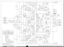
Wow , never looked at the 3b/4b ... what a "dogpile design".
Shunts everywhere to bandwidth limit the input stage (circled below).
miller , bootstrapped FB from the CFP's ..... 3 or more local FB loops ,
even some lead comp. from the output.
Looks like they knew they had a "squirrly" OPS and handicapped the
gain and bandwidth of the IPS to make it not smoke !! 😕
What is wrong with just a couple poles ?
OS
Attachments
Hi John,
This is one of the few cases where experience didn't hurt me!
Hi Brad,
-Chris
This is one of the few cases where experience didn't hurt me!
Hi Brad,
I'm going to bet that we are thinking of the same diagram. These were the separate sheets in a folded cover that RCA used to put out. Not in the transistor manuals. I was hoping to find that one to have a good look at it. I don't have them anymore. Darn.I think that was where I first saw the complementary feedback pair as output half.
-Chris
Hi ostripper,
It doesn't get any better as you look at it either. Now consider they used the cheapest parts they could get. Philips caps and resistors everywhere - back in the bad old days.
I don't know what they were trying to accomplish. It seemed to me that they fell in love with that output design and would stop at nothing to produce it. It took an engineer to break them of that bad habit. I wonder what he thought when he first laid eyes on this mess. I thought I had messed up the schematic as I was figuring it out. I had to keep checking physical connections, but it was really what they did. They were very confident that I couldn't figure it out when I warned them that I would trace the schematic out.
Oh well, now you have an image that you can't "unsee".
-Chris
Oh man, well said.Wow , never looked at the 3b/4b ... what a "dogpile design".
It doesn't get any better as you look at it either. Now consider they used the cheapest parts they could get. Philips caps and resistors everywhere - back in the bad old days.
I don't know what they were trying to accomplish. It seemed to me that they fell in love with that output design and would stop at nothing to produce it. It took an engineer to break them of that bad habit. I wonder what he thought when he first laid eyes on this mess. I thought I had messed up the schematic as I was figuring it out. I had to keep checking physical connections, but it was really what they did. They were very confident that I couldn't figure it out when I warned them that I would trace the schematic out.
Oh well, now you have an image that you can't "unsee".
-Chris
Hi ostripper,
Oh man, well said.
It doesn't get any better as you look at it either. Now consider they used the cheapest parts they could get. Philips caps and resistors everywhere - back in the bad old days.
I don't know what they were trying to accomplish. It seemed to me that they fell in love with that output design and would stop at nothing to produce it.
-Chris
I think they wanted a super fast output stage. They had slower devices
back then.
But , they found out it was unstable. Lots of CRO viewing later , they
shunted the hell out of the IPS to have a very low OLG.
I suppose they did what they had to - in the day.
Late 80's - bryston could of got some 35mhz Sankens (like the japanese).
An 80's toshiba/sanken EF3 will do 1/2kv- uS.
Then use just 1 miller and maybe a little lead compensation.
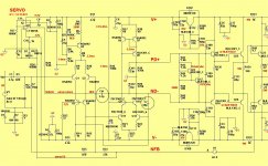
Our modern designs don't need all those caps - wow !! 😱 (below-symasui)
Just C7 will do - 1 cap !
PS- that amp runs cool , 60ma bias is the same after 1/2 year , 0
issues .... might last >25 years.
OS
Attachments
I think I saw it in a very late RCA transistor data book, but I may have hallucinated it.Hi John,
This is one of the few cases where experience didn't hurt me!
Hi Brad,
I'm going to bet that we are thinking of the same diagram. These were the separate sheets in a folded cover that RCA used to put out. Not in the transistor manuals. I was hoping to find that one to have a good look at it. I don't have them anymore. Darn.
-Chris
Ost,..........................
Our modern designs don't need all those caps - wow !! 😱 (below-symasui)
Just C7 will do - 1 cap !..............
do you know what voltage D6 generates?
It appears that the two transistors in the second stage run at ultralow Vce. Rough calculation using nominal Vbe values gives operating voltage of Q11 & Q12 @ ~ 0.7Vce.
I also note that the conventional SymaSym has the comp cap in the other leg of the second stage, i.e. across Q11, whereas this upside down SymaSym has the comp cap in the normal side, i.e. from Q1 collector and then across Q12+10
Any comments? Anyone.
Last edited:
Yet, look at the performance. I've had two of their power amps and one preamp over the years, and they worked reliably and flawlessly. Adcom, ditto; though I've only owned one of their power amps, it's had 30 years of reliable service.
Going surreal for a min
More from Mr. Matson on Day 2 | Stereophile.com
This takes audiophool worship to a new and slightly creepy level. For those unwilling to click, the boss of Kubotek was given Harry Pearson's record collection when he died and uses rips of those records to demo his equipment. So you can fondle a record HP owned whilst listening to a system playing the rip of it.
- Status
- Not open for further replies.
- Home
- Member Areas
- The Lounge
- John Curl's Blowtorch preamplifier part II