I read many posts concerning heatsinks temperature (mine run at 45°C, so no problems here), but what about transformer temperature.
I found that my Aleph J runs pretty hot, not only on the heatsinks but inside the case. When I opened it, I noticed that the transformer was very hot. I measured it at 70°C. I didn't manage to measure the temperature of the mounting plate, but I can't leave my finger on it more than two seconds before it hurts.
Is it a normal "behaviour" for a transformer or do I have a problem?
PS: The trafo is a 300VA toroïdal unit from Amplimo.
you should always ask, what is the ambient temperature?,
my amp's heatsink reads 45*C on an ambient of 30*C, barely warm when i touch it....
on your traffo do the 10 second hold hest, if you can stand the heat for 10 seconds, then not really a concern....
it is not the temperature per se, but how effcient can your chassis get rid of the heat...
listening to music your 300va traffo is probably putting out 30 watts at ear spltting volumes,
testing with sine waves and dummy loads otoh, that traffo will be stressed...
If the DC output from a capacitor input filter is 6.94Adc then the MINIMUM AC rating for the secondary is roughly twice that. i.e. ~14Aac.
In the simulation I set the load current at 3.4A (two channels at 1.7A per channel) and used the 5% regulation number from the transformer data sheet. The RMS secondary current was 6.94A.
Aleph J is usually biased at 2.6A per channel unless modified or are we talking about another amp now.In the simulation I set the load current at 3.4A (two channels at 1.7A per channel) and used the 5% regulation number from the transformer data sheet. The RMS secondary current was 6.94A.
find correct number and post it , just to prevent further confusion in already confused Greenhorn's minds
(ZM , eternal Greenhorn)
(ZM , eternal Greenhorn)
find correct number and post it , just to prevent further confusion in already confused Greenhorn's minds
(ZM , eternal Greenhorn)
When I built it (about 7 years ago) I was sure it was 2.6A.
I'll go back and measure it.
2.6 amps per channel would certainly explain a lot. I seem to recall the
design figure at about half that.
Also keep in mind that transformer suffers power factor - rectification to DC
makes pulses that heat up the transformer much more than simple
resistive load, so add another 30% or so to that wattage number.
23 Volts X 1.3 Amps X 2 polarities X 2channels X 1.3 power factor = 155 W
😎
2.6 amps per channel would certainly explain a lot. I seem to recall the
design figure at about half that.
Also keep in mind that transformer suffers power factor - rectification to DC
makes pulses that heat up the transformer much more than simple
resistive load, so add another 30% or so to that wattage number.
23 Volts X 1.3 Amps X 2 polarities X 2channels X 1.3 power factor = 155 W
😎
Glad your memory is better than mine. Maybe I am remembering max peak current as 2.6A per channel. I'm certain somehow I got 2.6A per channel somewhere, must have been max peak current through Active Current Source.
Manual says 2.5A but I'll check my amp again.
Papacase is nice enough for 70-80W of heat per channel , whatever he is writing in Greedy Boyz amusement literature .....
so , each article and SM needs to be read between the lines ........ for instance - Papadonut is twice 18Vac , which will never give 24Vdc per rail , at least not when loaded with proper A class amp ; he's simply calling his PSUs as twice 24 ........ number is nice 'n' round
so , always search for Papa's data about voltage across source resistor , simply because that is most secure data ...... rest of them are often copy-pasted either from older iteration of article or even from completely another amp , even if similar
that's from several reason , but most important ones are :
-he's humorous guy,
-it's cumbersome to fed eternal Greedy Boyz hunger , at speed they're expecting

so , for aleph J , without official article , lean on sole known data - 200W of power consumption from wall , for stereo amp
so , taking losses in account , that would be - roughly - 85W to 90W per channel;
assuming 22V5 rails .......... 90VA/(2x22V5) , means 2A
pretty much lower than 2A6 , if you ask me
these 600mA of difference isn't much per se , but it is muchoooo when you are cheapskating with copper and alumin(i)um
go figure
edit : even if my memory is playing with 1A6 value for Aleph J Iq ........ I'm not sure 100% , but I really don't care ; I'm always choosing my own way of disaster

Last edited:
Yeah 2 A is probably correct.
Active current source must put out I = (P/R)^0.5
(50/8)^0.5 = 2.5A max through active current source. Which is close to my 2.6A figure.
Or (26/4)^0.5 = 2.55A
Ok I'm satisified I'm not going crazy.
Active current source must put out I = (P/R)^0.5
(50/8)^0.5 = 2.5A max through active current source. Which is close to my 2.6A figure.
Or (26/4)^0.5 = 2.55A
Ok I'm satisified I'm not going crazy.
Last edited:
One more possibility.
It might have been 2.6A total into 3 pairs which would be close to 1.7A total into 2 pairs.
I have Peter Daniel boards. I'll go back and check the amp.
It might have been 2.6A total into 3 pairs which would be close to 1.7A total into 2 pairs.
I have Peter Daniel boards. I'll go back and check the amp.
The schematic posted by Zen Mod in this thread http://www.diyaudio.com/forums/pass-labs/111197-aleph-j-schematic.html shows two FETs per rail. The link in Nelson's post is broken.
In reply 17 the OP confirmed the bias is set per the user manual at ( 0.4V / 0.47 Ohm) X 2 = 1.7A per channel assuming 2 FETs per rail.
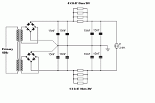
Based on the OP's description and the DIY store's pic I assume the schematic is as in the first attachment below.
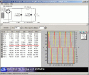
I assumed that the line frequency in France is 50Hz. You can see that the simulation runs for 5 complete cycles which is important for the RMS calculation.
The schematic was simplified to run the simulation in the second attachment. The program estimates open circuit secondary Voltage and source impedance from the Nominal secondary Voltage of 36V and 5% regulation. ESR of the capacitors is just a guess.
Results show peak secondary current of 17.5A and RMS current of 6.95A. Multiplying the RMS current by the nominal secondary Voltage gives 250.2 VA.
Attachments
The only difference between that Papa's circuit and my Papa's circuit is my Papa's circuit takes feedback directly from speaker side of C3 and not through R20 to R23.
Last edited:
The link is broken but not his attached document.The schematic posted by Zen Mod in this thread http://www.diyaudio.com/forums/pass-labs/111197-aleph-j-schematic.html shows two FETs per rail. The link in Nelson's post is broken.
- Status
- Not open for further replies.
- Home
- Amplifiers
- Pass Labs
- Transformer temperature

