soundcard and free software get you a long way with fft, averaging and much simpler hardware
I know. Unfortunately we don't have a single working computer in the house at the moment, I get online via a Samsung galaxy tablet. It's frustrating because you can't get LTspice for Android OS either.
However, I am learning a lot about analog instrumentation, through this endeavour. That in itself has been very rewarding.
It just occurred to me today that there could be issues with input offsets at the inputs to the multiplier so have been making a few last minute modifications to the circuit. I'm almost scared to switch it on in case a mistake could damage the costly multiplier chip!
locally old PCs can be found, had for free - although the recycling center doesn't let you take the ones turned in to them because of privacy concerns about people's personal data on the hard drive
locally old PCs can be found, had for free - although the recycling center doesn't let you take the ones turned in to them because of privacy concerns about people's personal data on the hard drive
All I really need is a motherboard and CPU, I have a case with PSU, I also have a 300GB HDD and a DVD drive. Almost forgot, I'd need RAM also. 🙂
In fact, you don't need delicate and expensive IC's: a synchronous detector can be made using three or four cheap CD4000's, and it will not only be robust and offset-immune, but it will also vastly outperform anything based on a soundcard + the best software in the world: if you are careful with charge injection, layout, etc, extraction of signals having negative S/N in excess of 60dB is possible at audio frequenciesIt just occurred to me today that there could be issues with input offsets at the inputs to the multiplier so have been making a few last minute modifications to the circuit. I'm almost scared to switch it on in case a mistake could damage the costly multiplier chip!
not sure I buy that proposition - soundcards and PCs can average for days if wanted
while analog low pass filters after synchronous detectors are hard to make with 100s of seconds time constants from self leakage, DA of even very good capacitors
I have averaged 100 second fft records with some clean low noise amplification in front of my ESI Juli@ and seen -160 dB noise floor in actual plots when the gain is factored in
Yes they can, but that doesn't mean they do something useful: each time you double the averaging time, you should gain 3dB of noise floor, because it is equivalent to reducing the bandwidth, but past some point there will be no more improvement.not sure I buy that proposition - soundcards and PCs can average for days if wanted
100s is equivalent to a bandwidth of ~0.0016Hz, but to fully exploit the low noise it should provide, the clock must have a matching stability and the ADC must have a low jitter, and a quantization noise looking random enough.
DA is annoying because it makes the settling time longer than it should be, but basically it does not compromise performance (or very little).while analog low pass filters after synchronous detectors are hard to make with 100s of seconds time constants from self leakage, DA of even very good capacitors
In fact, you don't need delicate and expensive IC's: a synchronous detector can be made using three or four cheap CD4000's, and it will not only be robust and offset-immune, but it will also vastly outperform anything based on a soundcard + the best software in the world: if you are careful with charge injection, layout, etc, extraction of signals having negative S/N in excess of 60dB is possible at audio frequencies
I haven't come across any based on CD4000, though I was aware there were cheaper ways of implementing this function. I happened to already have an MPY634KP, strange as that may seem! ( I stocked up on a huge amount of components about 5 years ago when I had some spare cash to spend ) So it looked like the most straightforward way to do it.
If I accidently destroy the mpy634, I will definitely be looking to build a cheaper synchronous detector, possibly with an OTA, I also have a few, lm13700 and ca3080, lying about.
not sure I buy that proposition - soundcards and PCs can average for days if wanted
while analog low pass filters after synchronous detectors are hard to make with 100s of seconds time constants from self leakage, DA of even very good capacitors
I have averaged 100 second fft records with some clean low noise amplification in front of my ESI Juli@ and seen -160 dB noise floor in actual plots when the gain is factored in
This guy Gary Pimms claims to have measured 100Gohm in current sources with a soundcard and a TL084 based amplifier.
Last edited:
100s is equivalent to a bandwidth of ~0.0016Hz, but to fully exploit the low noise it should provide, the clock must have a matching stability and the ADC must have a low jitter, and a quantization noise looking random enough.
noise is random enough when you are trying to pull signal out of the noise floor with these techniques
and when using modern 24 bit Delta-Sigma converters that are todays mode for audio ADC/DAC the electronics' random noise is always more than enough for effective dithering
and the most common Delta Sigma converters for audio have differential linearity way down into the noise floor
most soundcards use their own clock for both ADC and DAC so they are correlated over long times
only the difference in DAC/ADC latency gives a window of jitter sensitivity with common clocking from the same xtal osc
crosstalk, spurs and interference are more likely limits - spurs and interference can be avoided by simply looking, moving your test frequency
the averaging strategy can be modified too - make many shorter records with randomly delayed start times - then any steady interference will also tend to get averaged out
soundcards, free software are great tools for ridiculous low price that deserve serious consideration in audio measurement
I will almost certainly try the soundcard+PC approach when I am in a position to do so. Experimenting with analog instrumentation, has been to date, incredibly rewarding and achingly frustrating at the same time, but overall it has been a learning experience and having yet to complete the construction and testing of all of my proposed ideas, I am yet to be convinced that I have established the best possible means of accurately measuring CCS impedances.
I am still unable to decide whether measuring the CCS' ac current is better done in the top branch ( with a jfet: One of Elvees suggestions ) OR with a resistor in the negative branch. ( As suggested by UDOK and was used in Gary Pimms setup.) There is a measured difference, but I lack the ac circuit analysis skills to explain the differences, Feel free to offer any ideas as to the why of these differences.
Not forgetting that Elvee proposed and tested a transformer method, which is still another possibility, my only concern is in finding one that will work at 20Hz ( pro-audio mic transformer??? ), as that is where the really high impedances are to be found.
Udo, are you still following this thread, I havent heard from you in ages?
The lock in amplifier didn't work. The mpy634 didn't work! Either it was a dud or a bad fake, but even with clean signals it didn't multiply. I am trying a transformer now, though its not screened, so might not work well at higher frequencies. I will keep updating as I make further investigations.
Elvee, can you point me in the direction of the CD4000 based lock in amplifier, I have searched and can only come across circuits for digital signals. Did you mean, using analogue switches like 4066, 4053, etc?
Elvee, can you point me in the direction of the CD4000 based lock in amplifier, I have searched and can only come across circuits for digital signals. Did you mean, using analogue switches like 4066, 4053, etc?
I know. Unfortunately we don't have a single working computer in the house at the moment, I get online via a Samsung galaxy tablet. It's frustrating because you can't get LTspice for Android OS either.
You can get a trial subscription for TINA-Cloud. It's the sim software used by TI.
Thanks, jackinnj, I tried it and couldnt get it to work on google chrome on my android tablet. I have a basic simulator that is handy for vtrying out ideas, but its models are generic, rather than part specific.
I was looking at something along these lines. I have 4066's and 4053's. I have a draught schematic though it's not complete yet.
I am going to try the transformer, mainly because the LT1128 requires around a 100 ohm source resistance for low noise performance. Its current noise is high at 12pA/√Hz, so with a 1 K current sense resistor there'd be 12 nV/√Hz noise! Also the transformer should help with ground loop problems. ( at the risk of picking up hum from stray magnetic fields! )
I imagine Elvee is thinking along these lines
I was looking at something along these lines. I have 4066's and 4053's. I have a draught schematic though it's not complete yet.
I am going to try the transformer, mainly because the LT1128 requires around a 100 ohm source resistance for low noise performance. Its current noise is high at 12pA/√Hz, so with a 1 K current sense resistor there'd be 12 nV/√Hz noise! Also the transformer should help with ground loop problems. ( at the risk of picking up hum from stray magnetic fields! )
Last edited:
Yes, that is the idea, in its most basic form.I imagine Elvee is thinking along these lines
For an amplifier (not part of a servo system), the gain of the detector would need to be defined, and a high gain (also defined) AC amplifier would be placed upstream of the synchronous detector.
Even a simple arrangement like this one would already work quite well, but if you want to extract signals many tens of dB lower than the noise, improvements and refinements have to be added: double balanced topology is the most obvious as it will cancel many charge-injection effects, but it is possible to go much further, simply with clever arrangements and without spending much in complexity, cost, or exotic components.
Of course, life is easier with high performance switches, like the Linear one (I don't remember the exact reference).
I'll try to locate more evolved examples of detectors.
This is my idea based on some circuits that I've seen online. The DC bias is necessary because of the limited supply range of the CD4053. This section would be powered with the +12 V supply. With a better analog switch the full +/- 12 VDC would be used.
Attachments
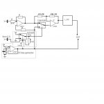
It should work, except for the driving signal of the 4053: a Schmitt trigger is not suitable, because it will introduce a phase delay, and timing inaccuracies.This is my idea based on some circuits that I've seen online. The DC bias is necessary because of the limited supply range of the CD4053. This section would be powered with the +12 V supply. With a better analog switch the full +/- 12 VDC would be used.
You should use a comparator instead.
Also remember that the reference signal needs to be in phase with the signal to be demodulated.
This will be the case if the measured impedance is purely resistive, but in general there will be some phase shift, and you should include a provision to be able to shift the reference signal (you tune the phase shift to read the maximum amplitude).
A way of doing that automatically is to use two demodulators in quadrature and compute the vector magnitude, but it adds complexity.
Posted by Elvee: It should work, except for the driving signal of the 4053: a Schmitt trigger is not suitable, because it will introduce a phase delay, and timing inaccuracies.
You should use a comparator instead.
This actually occurred to me last night when I was falling asleep!
If the reference signal was exactly 180° out of phase, surely the output would be a negative voltage of the same amplitude as the in phase result?
Yes of course: maximum output for 0°, null for + or - 90° and negative for 180°This actually occurred to me last night when I was falling asleep!
If the reference signal was exactly 180° out of phase, surely the output would be a negative voltage of the same amplitude as the in phase result?
Shopping trip today:
I bought a couple of these analogue switches to try out something similar as above, but without the supply rail limitations. Charge injection, is only 1 picoColoumb. I also bought some 0.1% MF resistors for the input stage. There are some pretty expensive resistors out there, I was surprised!
I also bought 4 DN2540N3 MOSFETs to try out as current sources, as Gary Pimms claims to have made a 200G CCS with 2 of these, I am sceptical about this but want to try it out for myself.
Last edited:
Today I was investigating the performance of my aforementioned transformer. It really isn't well suited to this application as the frequency response is far from flat, but more problematic is the degree of phase shift that it introduces, would cause havock regarding the use of lock in amplification further down the signal chain.
Also my components arrived today, this time next day delivery, meant next day delivery. Well done Farnell!
Also my components arrived today, this time next day delivery, meant next day delivery. Well done Farnell!
- Status
- Not open for further replies.
- Home
- Amplifiers
- Solid State
- How do you calculate impedance of a current source?