I'm using the LM384 chip amp (2 of them for stereo) and I'm summing both channels' inputs into a dual op amp to correct the polarity and then low pass filter the signal for a subwoofer output. I am having some real problems with the LM384 oscillating at around 500kHz when the op amp is hooked up to power.
The chip amp runs off of a single supply and I am trying to use that same supply to power the op amp too using a virtual ground. Is this not a good idea?
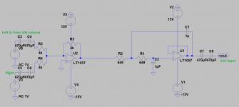
The linear pot is being used as a quasi log pot with the 1.33k R after it. The circuit still oscillates with the R removed. I've isolated the op amp's input and outputs from DC with series blocking caps.
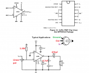
Here is the datasheet: http://www.ti.com/lit/ds/symlink/lm384.pdf
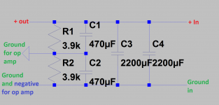
I've attached the schematic of the chipamp, op amp and capacitor reservoir/virtual ground.
The chip amp runs off of a single supply and I am trying to use that same supply to power the op amp too using a virtual ground. Is this not a good idea?
The linear pot is being used as a quasi log pot with the 1.33k R after it. The circuit still oscillates with the R removed. I've isolated the op amp's input and outputs from DC with series blocking caps.
Here is the datasheet: http://www.ti.com/lit/ds/symlink/lm384.pdf
I've attached the schematic of the chipamp, op amp and capacitor reservoir/virtual ground.
Attachments
Is there a way to run this single supply chipamp and an op amp from the same unregulated supply? Cheapest way out.
What makes this not work? My thinking was to provide the op amp with a virtual ground point and to block DC into the input/output of the op amp that it shares with the input of the chipamp with the series 470uF caps.
What makes this not work? My thinking was to provide the op amp with a virtual ground point and to block DC into the input/output of the op amp that it shares with the input of the chipamp with the series 470uF caps.
Last edited:
> Is there a way to run this single supply chipamp
> and an op amp from the same unregulated supply?
The negative supply pin of the op-amp goes to ground.
Positive supply pin of op-amp to supply voltage (same as 384)
but the non inverting input pin goes to 1/2 of the supply voltage.
Remove C1 to make 1/2 voltage point.
> and an op amp from the same unregulated supply?
The negative supply pin of the op-amp goes to ground.
Positive supply pin of op-amp to supply voltage (same as 384)
but the non inverting input pin goes to 1/2 of the supply voltage.
Remove C1 to make 1/2 voltage point.
c3 || c4 has no reason, use a single bigger cap.
for the opamp make a voltage divider out of 2 resistors, rated at 1 watt.
use regulator to keep the supply stable for the opamp.
for the opamp make a voltage divider out of 2 resistors, rated at 1 watt.
use regulator to keep the supply stable for the opamp.
c3 || c4 has no reason, use a single bigger cap.
for the opamp make a voltage divider out of 2 resistors, rated at 1 watt.
use regulator to keep the supply stable for the opamp.
C3 & C4 are a cap reservoir for transients for the 2 chipamps. For some reason if I tried to get the 2 2200uF caps close to the chipamp pins, the chips became unstable and oscillated. This is without the op amp connected or the divider. I found a place in the middle of the 2 chipamps where the oscillation did not happen so I tied them together along with the divider for the virtual ground reference. I don't recommend using the LM384. It is very unstable.
Don't you see that I did make a divider for the op amp? I am not going to use regulators.
Remove C1 to make 1/2 voltage point.
On the 1st pic the ground for the op amp is the 1/2 voltage point. How would removing C1 stop the problems with oscillation?
Hi,
What part of standard AC single rail design for op-amps do
people not understand ? Virtual grounds are not needed.
rgds, sreten.
What part of standard AC single rail design for op-amps do
people not understand ? Virtual grounds are not needed.
rgds, sreten.
Last edited:
The object is to make the 1/2 point as clean as possible.
(As clean as ground, but with DC)
The capacitor to the positive supply allows a path for AC
from the supply to the signal input.
(As clean as ground, but with DC)
The capacitor to the positive supply allows a path for AC
from the supply to the signal input.
Right .... I'd say a misnomer in this case ....Hi,
What part of standard AC single rail design for op-amps do
people not understand ? Virtual grounds are not needed.
rgds, sreten.
The two voltages from the same supply are used as ground, in effect it is shorting these two.
The simplest solution will be to use another transformer for supplying the dual supply to the op-amp. A small center tapped transformer of 18VCT(9V-0-9V), a bridge rectifier using 4x 1N400x and two filter capacitors 2x 1000microfarad will be needed.
Gajanan Phadte
The transformer you are using, is it center tapped...
Last edited:
No center tap on this one.
I'm starting to believe that the chip is the problem here. These chips are by far the most unstable thing I've experienced. For example, if I bridge a 2200uF cap in parallel with the 100nF ceramic which is across the power pins of the chip, it will throw it into oscillating. This chip oscillates if you turn the volume all the way down or up and in many other situations as well.
I'm calling TI today to complain. I do not recommend using the LM384
That'll fall on deaf ears 🙂 Do you have any idea how old that chip is?
Oscillations are very common in these old single supply chips. Any time you share a power ground and signal ground you are Asking For Trouble. There is probably only one possible PCB layout that's stable and the other 3500 aren't. The other thing they don't tell you is to put resistors of a few k in series with BOTH inputs so it doesn't oscillate when you turn the volume all the way down.
Oscillations are very common in these old single supply chips. Any time you share a power ground and signal ground you are Asking For Trouble. There is probably only one possible PCB layout that's stable and the other 3500 aren't. The other thing they don't tell you is to put resistors of a few k in series with BOTH inputs so it doesn't oscillate when you turn the volume all the way down.
Your problem is not the Op Amp or the Chip amp but poor grounding and lack of experience.
FWIW all my projects oscillated, even if I grounded everything, shielded the cabinet, used shielded wire everywhere, even for power lines ................... 45 years ago 😉
Now I build naked circuits on the table, no chassis, with plain unshielded wire ... and have no problems.
TI will tell you exactly the same.
> I do not recommend using the LM384
Send me your extras 🙂 ..... I think they are a nifty chip for the way they dissipate
heat. Stable for me. You might try these :
http://www.onsemi.com/PowerSolutions/product.do?id=LA4425A
hyperstable
Send me your extras 🙂 ..... I think they are a nifty chip for the way they dissipate
heat. Stable for me. You might try these :
http://www.onsemi.com/PowerSolutions/product.do?id=LA4425A
hyperstable
Last edited:
The LM384 datasheet circuits show only 100nF bypass caps. You may see some benefit with an additional 47 or 100 uF cap, but 2200uF is better used in the power supply.C3 & C4 are a cap reservoir for transients for the 2 chipamps. For some reason if I tried to get the 2 2200uF caps close to the chipamp pins, the chips became unstable and oscillated.
Same with the series 470uF coupling caps. There's no way the LF -3dB point needs to be that low.
Many of these little old chip amps have high input impedance. 150k in this case. They need extra care to prevent oscillation. I suggest getting it to work first, then work on connecting your active summer/filter to it.
I think gmphadte is right. You cannot use a single supply chipamp and an op amp with a virtual ground from the same power supply even if you isolate the grounds from each other with DC blocking caps. You need separate transformers or more than one secondary tap.
My problem with stability I think is most likely coming from the chips being damaged from inrush current when they are switched on. I am switching the power on after the bridge rectifier and I am using 4400uF of local cap reservoir for transients. When I measured the peak current when switched on, the chip was getting up to 35.5A of inrush current. I think this has been damaging the chips I've used leaving them unstable or almost completely shorted. When I use 100nF as the local cap, the peak current transient was around half an amp. Here is the post that helped me discover this: http://www.diyaudio.com/forums/chip-amps/92844-chips-blow-up-when-powering-amp.html
I wanted to keep the local caps at 4400uF so I ended up putting 3- 10 ohm R's in parallel that came to a series value of 3.22 ohms, right in front of the 2- 2200uF caps. This reduced the peak current transient to 4 amps which so far the new chip is dealing with.
I switched to the TPA1517NE stereo 6W chip. No need for a Zobel on this one but it is still single supply. Here is the completed project. I use 8 layers of heavy duty aluminum foil to cover the bottom and top of the "chassis" (cut out a holes for the air to have an intake and exit point from the chip) then I tie that to ground which isn't shown in the following pictures. The heat sink is made from copper roof flashing and tied to the chip using thermal compound. I wrapped a thick copper packing staple across the ground pins making contact with all of them on top of the board close to the package, had a row of copper wire soldered to the board behind that and used plenty of solder underneath the board. This chip sustained maximum output for both channels into 4 ohms for 2 minutes and it was warm but not hot.


Now some tests. The following figures are in peak watts. I don't mess with RMS. Pushing the chip right to it's limits of clean playback at 1kHz using only 1 channel for a non inductive dummy load:

The left channel drops 1.6 watts (4ohm) and 0.8W (8ohm) when the right channel is given a load as well:

The chip is able to do a CEA burst transient at 1kHz cleanly 3.2 watts (4ohm) and 1.3 watts (8ohm) higher than a sustained tone. I haven't tested it but I bet if I take the local cap reservoir out of the equation that would change:

Here is the frequency response for using a 100nF input cap and a 1000uF output cap:

I am happy with this chip. TI was very understanding of my situation and sent me a few TPA1517's for samples, thanks Texas Instruments, you guys are the coolest! Even though my layout is on strip board, when I turn the volume all the way up, I don't hear anything when I put my ear to the speakers which are wired 2 on each channel in series giving a 9 ohm DC reading.
My problem with stability I think is most likely coming from the chips being damaged from inrush current when they are switched on. I am switching the power on after the bridge rectifier and I am using 4400uF of local cap reservoir for transients. When I measured the peak current when switched on, the chip was getting up to 35.5A of inrush current. I think this has been damaging the chips I've used leaving them unstable or almost completely shorted. When I use 100nF as the local cap, the peak current transient was around half an amp. Here is the post that helped me discover this: http://www.diyaudio.com/forums/chip-amps/92844-chips-blow-up-when-powering-amp.html
I wanted to keep the local caps at 4400uF so I ended up putting 3- 10 ohm R's in parallel that came to a series value of 3.22 ohms, right in front of the 2- 2200uF caps. This reduced the peak current transient to 4 amps which so far the new chip is dealing with.
I switched to the TPA1517NE stereo 6W chip. No need for a Zobel on this one but it is still single supply. Here is the completed project. I use 8 layers of heavy duty aluminum foil to cover the bottom and top of the "chassis" (cut out a holes for the air to have an intake and exit point from the chip) then I tie that to ground which isn't shown in the following pictures. The heat sink is made from copper roof flashing and tied to the chip using thermal compound. I wrapped a thick copper packing staple across the ground pins making contact with all of them on top of the board close to the package, had a row of copper wire soldered to the board behind that and used plenty of solder underneath the board. This chip sustained maximum output for both channels into 4 ohms for 2 minutes and it was warm but not hot.
Now some tests. The following figures are in peak watts. I don't mess with RMS. Pushing the chip right to it's limits of clean playback at 1kHz using only 1 channel for a non inductive dummy load:
The left channel drops 1.6 watts (4ohm) and 0.8W (8ohm) when the right channel is given a load as well:
The chip is able to do a CEA burst transient at 1kHz cleanly 3.2 watts (4ohm) and 1.3 watts (8ohm) higher than a sustained tone. I haven't tested it but I bet if I take the local cap reservoir out of the equation that would change:
Here is the frequency response for using a 100nF input cap and a 1000uF output cap:
I am happy with this chip. TI was very understanding of my situation and sent me a few TPA1517's for samples, thanks Texas Instruments, you guys are the coolest! Even though my layout is on strip board, when I turn the volume all the way up, I don't hear anything when I put my ear to the speakers which are wired 2 on each channel in series giving a 9 ohm DC reading.
Last edited:
- Status
- Not open for further replies.
- Home
- Amplifiers
- Chip Amps
- LM384 and op amp from same supply...