Hi bmwparts,
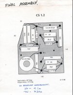
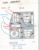
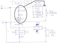
It would make more sense to me if the connections to the crossover were made as I've shown attached. However, that 20R resistor in the tweeter circuit provides a DC path from the amplifier through to the tweeter, which is very unusual. Hope this helps.
Peter
It would make more sense to me if the connections to the crossover were made as I've shown attached. However, that 20R resistor in the tweeter circuit provides a DC path from the amplifier through to the tweeter, which is very unusual. Hope this helps.
Peter
Attachments
Shouldn't the 1.6mH inductor be connected to the tweeter + ?
Hi AllenB,
Agreed, the 1.6mH inductor is connected to the tweeter when the Xover is connected as I show in my post No.2. Also, the 3xcapacitors in parallel+10R in series should be connected across the wooferl, not across the amplifier output. This is also shown in my post No.2.
Peter
beamer,
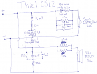
your schematic is correct except for the RCL network of the
tweeter part which should be in parallel with the tweeter and
the other thing is, you have separate amp terminals for the
tweeter and the woofer, as if it had biwiring terminals, according
to the assembly picture.
your schematic is correct except for the RCL network of the
tweeter part which should be in parallel with the tweeter and
the other thing is, you have separate amp terminals for the
tweeter and the woofer, as if it had biwiring terminals, according
to the assembly picture.
beamer,
your schematic is correct except for the RCL network of the
tweeter part which should be in parallel with the tweeter and
the other thing is, you have separate amp terminals for the
tweeter and the woofer, as if it had biwiring terminals, according
to the assembly picture.
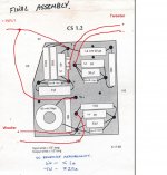
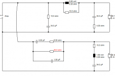
so if I move the RCL to this location it should be accurate?
The CS1.2 actually doesn't have biamp terminals, unfortunately. It goes to a standard two binding post connector, despite the crossover layout. Thiel seems to do that with almost all of their speakers for some reason.
Attachments
so if I move the RCL to this location it should be accurate?
Exactly.
The CS1.2 actually doesn't have biamp terminals, unfortunately.
You could modify that to your needs if really necessary.
We had a look at this time-aligned speaker before.
http://www.diyaudio.com/forums/multi-way/265242-can-thiel-cs1-2s-upgraded-6.html#post4430479
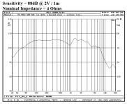
Did seem to be a 4 ohm Vifa P17WJ polycone, as it goes. Robust SEAS metal tweeter with Fs notch. Impedance correction on woofer.
http://www.diyaudio.com/forums/multi-way/265242-can-thiel-cs1-2s-upgraded-6.html#post4430479
Did seem to be a 4 ohm Vifa P17WJ polycone, as it goes. Robust SEAS metal tweeter with Fs notch. Impedance correction on woofer.
Attachments
Last edited:
I completely forgot about that thread! Thanks for reminding me. However, I don't think your schematic is correct. Where are you finding that extra CR in parallel with the woofer? and that resistor that lets DC to the tweeter?
I guess the parallel resistor is correct ! It helps to "truncate" the highpass function such that a first order acoustic rolloff can be approached (at least to some degree).
Regards
Charles
Regards
Charles
Last edited:
I completely forgot about that thread! Thanks for reminding me. However, I don't think your schematic is correct. Where are you finding that extra CR in parallel with the woofer? and that resistor that lets DC to the tweeter?
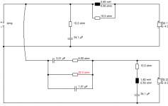
That weird 20R resistor to the tweeter was always there, but the 4R + 30uF Zobel was something I was adding in subsequent modelling. So I think the actual filter looks like below. It is common enough to put a 10R resistor across the bass coil to get a nearer flatter butterworth response. These are 6dB filters AFAIK. 10R plus 34.1uF is pure impedance correction that you could lose with a transistor amp.
But I still don't like the 20R resistor. It sends too much distorting bass to the tweeter, however purist you get about slopes. It means it distorts badly at loud.
Attachments
Yes the 20R is perplexing.. I believe it could be improving the response. I think it may continue to do this if it had a large capacitor in series with it. I think another way could even be found to do the same thing. I guess it would require more components...
That weird 20R resistor to the tweeter was always there, but the 4R + 30uF Zobel was something I was adding in subsequent modelling. So I think the actual filter looks like below. It is common enough to put a 10R resistor across the bass coil to get a nearer flatter butterworth response. These are 6dB filters AFAIK. 10R plus 34.1uF is pure impedance correction that you could lose with a transistor amp.
But I still don't like the 20R resistor. It sends too much distorting bass to the tweeter, however purist you get about slopes. It means it distorts badly at loud.
Ahh, I see. Yes, I do notice that they don't like to go loud. Things did improve when I actively crossed the 1.2s at 60hz with some 10" Vifas.
How noticeably will removing the 20R change the sound? And what will change if I add the Zobel?
Yes the 20R is perplexing.. I believe it could be improving the response. I think it may continue to do this if it had a large capacitor in series with it. I think another way could even be found to do the same thing. I guess it would require more components...
What would you add, Allen?
I'd like to give you a comprehensive answer but good crossover design takes time. However, the large capacitor I suggested in series with the 20R (and only there, within that block) won't change anything if it is large enough so it can be put there with little concern.
The idea is that the capacitor cuts the resistor out of circuit below some frequency. If you let it be in circuit around and below the crossover frequency you could get the best of both worlds. Maybe try having the capacitor equal 20 ohms a couple of octaves below the crossover as a start.
The idea is that the capacitor cuts the resistor out of circuit below some frequency. If you let it be in circuit around and below the crossover frequency you could get the best of both worlds. Maybe try having the capacitor equal 20 ohms a couple of octaves below the crossover as a start.
Looking at it in a bit more detail, the 3uF=6.5ohms around 8kHz so that branch will be resistive above that frequency. The tweeter impedance is probably rising there so it may have a smaller effect wrt the top end. It is also shunted by the 1uF capacitor which will bring down the series impedance toward 20kHz so I'd guess this could result in a dip around/above 8k.
The 20ohm resistor limits the maximum series impedance. The 1uF is around 20R also at 8k. Looking below this, say 4kHz, the 1uF is around 40R but the 3uF-6.5 branch would be more like 15R so this is where most of the current would be flowing and the 1uF capacitor will have a less significant role at lower frequencies.
At lower frequencies the attenuation will be limited to the effect of the 20R resistor and the capacitor branches will drop from significance. If the tweeter impedance was say, 5 ohms down there you'll get a maximum attenuation of around 12dB.
Removing the 20R doesn't affect things much at all, except take the slope steeper below 1.5kHz on the tweeter. It's all more conventional in fact.Ahh, I see. Yes, I do notice that they don't like to go loud. Things did improve when I actively crossed the 1.2s at 60hz with some 10" Vifas.
How noticeably will removing the 20R change the sound? And what will change if I add the Zobel?
Capacitor followed by LCR Fs correction is quite an established technique for shallow slopes. Joe Rasmussen uses it in the Elsinore. It's in the Audio Note stable too.
http://www.diyaudio.com/forums/multi-way/147632-classic-monitor-designs-17.html#post4358469
BTW, it's worth measuring that woofer DCR to confirm it's 4 ohms. The Zobel would be different if it's 8 ohms.
Fitting a bass zobel, which here is around 4R plus 30uF IMO, is another standard game, especially with polycones. But it would do things to the slopes and the phase response and hence tweeter polarity I reckon, because it's nearer 12dB/octave LR2. It will send more current through the 10R resistor though, which you might also remove along with the impedance correction if you are trying big changes.
Attachments
Last edited:
- Home
- Loudspeakers
- Multi-Way
- Have I properly translated this Thiel crossover diagram to a schematic?