Hi all,
I just finished building a 15W tube guitar amp at an amp building course. It worked fine when I finished the course, but when I got home it wouldn't work. The 2 power tubes glow, but only one preamp tube glows. I swapped the two preamp tubes around to check if it's a bad tube but it worked in the other spot. I'm getting no guitar sound from the speaker except a very gentle hum that responds to the master volume control.
I've checked all my soldering and it all looks and feels fine.
What do I check now?
All help is very much appreciated.
The 2 power tubes glow, but only one preamp tube glows.
Trace out the heater wiring very carefully. The socket with no heater glow is wired wrong.
You can use a DVM to measure the AC voltage on the heater tube pins.
 Moving to I&A since this is a guitar amplifier.
 Recheck for broken wires and cold solder joints, bad socket pin?
The weird thing is that it worked perfectly after the course, I drove home (amp in suitcase flat on the floor of the car- no movement- it was also on a soft blanket to give it some 'suspension'), then it didn't work, so it had been wired correctly at one point.
How exactly do I measure the AC voltage on the heater tube pins?
How exactly do I measure the AC voltage on the heater tube pins?
Please post more details, schematic [hand drawn or excerpt, plse do not post copyrighted materials here] and pictures of amp showing internals.
Also with soldering- all the joints seem to be holding solidly but I know that doesn't always mean a proper connection. Is there a way to visually see a bad solder connection?
The weird thing is that it worked perfectly after the course, I drove home (amp in suitcase flat on the floor of the car- no movement- it was also on a soft blanket to give it some 'suspension'), then it didn't work, so it had been wired correctly at one point.
How exactly do I measure the AC voltage on the heater tube pins?
Do you have a digital multimeter, and what tubes specifically are used?
Also with soldering- all the joints seem to be holding solidly but I know that doesn't always mean a proper connection. Is there a way to visually see a bad solder connection?
Sometimes obvious, sometimes not, reheat both filament connections.. If you have a meter check for continuity at the filament pins with the tube removed. You should have a very low resistance if the pins are still properly connected to the transformer filament winding.
Yes I have a digital multimeter.
The tubes are russian- all I know is the code on the side is 6H2n (although the N looks like a russian symbol) then below that is 08-83
The tubes are russian- all I know is the code on the side is 6H2n (although the N looks like a russian symbol) then below that is 08-83
When you say check for continuity at the filament pins...(sorry for the complete novice questions by the way)...is that checking the resistance from pin 1 to pin 2 and then through each of the 9 pins?
Yes I have a digital multimeter. the code on the side is 6H2n
Look very carefully at pins 4 and 5 on the bad socket. Probably one of the wires connecting to one
of those pins is not soldered. It's unlikely that a new socket has a bad pin. Also, one of the wires
could be broken because of a nick when you stripped it.
Last edited:
Transporting the amp on the floor of the car is bad idea.....micro engine vibrations cause destroying of solders inside, if soldering was bad and the wires wasn't properly cleaned.......
Last edited:
It doesn't matter if it seems like nothing could have happened to it on the trip home, but something happened, because it doesn't work.
Since it worked before, it is probably wired right, but probably not well. In other words a connection you made didn't hold up. In most amps the heater power comes through a pair of wires going socket to socket. So in the socket that won't light a tube, most likely either one or the solder connections on that socket needs to be redone OR one of the connections at the next socket over. The last working socket has two wires coming to it from the power source, and two more wires that continue to the dead socket If one of those continuing wires is not well soldered, then current won't reach the next tube.
But all in all it sounds like at most four connections are suspect, so just resolder all the heater connections in the dark socket, and the one next to it.
Take the tube out, and put the meter probe into the socket from the outside of the chassis (where the tube would be), into pin 4 and then pin 5 and pin 9, and check continuity to heater transformer.
Unfortunately I've found that even new sockets can have loose pins.
6N2P is russian "close enough" substitute for 12AX7, with a little bit lower gain. It's a good tube if old stock, as your tube appears to be.
Unfortunately I've found that even new sockets can have loose pins.
6N2P is russian "close enough" substitute for 12AX7, with a little bit lower gain. It's a good tube if old stock, as your tube appears to be.
Thanks so much to all of you for your help. I have learnt so much from you all and didn't expect so many replies. I have fixed the problem- it ended up being a loose solder joint that looked and felt like it was connected but with a slightly harder jiggle it came loose, so I resoldered it and success. Thanks again guys!!!
I had the same problem with input potentiometer in airplane - 9 hours, that connectors inside was broken......contacts was 0.
Last edited:
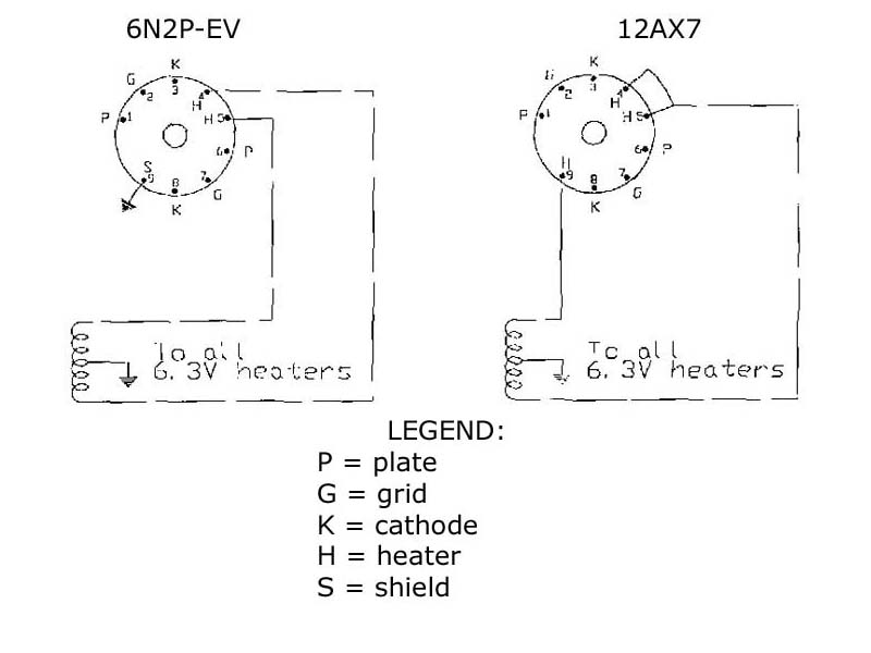
It's close enough ... except on heater wiring 🙂Take the tube out, and put the meter probe into the socket from the outside of the chassis (where the tube would be), into pin 4 and then pin 5 and pin 9, and check continuity to heater transformer.
Unfortunately I've found that even new sockets can have loose pins.
6N2P is russian "close enough" substitute for 12AX7, with a little bit lower gain. It's a good tube if old stock, as your tube appears to be.
Description above applies to 12A*7 family, where there's one 6.3V filament from pins 4 to 9 and another from 5 to 9 ; but 6N2P has both 6.3V filaments in parallel from pin 4 to 5 , and they do not have continuity to pin 9, which is an internal shield and should be grounded if possible.
- Status
- Not open for further replies.
- Home
- Live Sound
- Instruments and Amps
- Help - valve won't fire