It had to do with the value of the resistors around the transistors....
I found that it was to costly to have all of those resistors and have poor performance too.
When adding a simple opamp was all that was needed.
MOSFET's can be used quite easily, in fact very first the version I made used a LM317 for the voltage control and I used it to feed an IRF512 FET that fed the base's of four paralleled 2N3055's....jer 🙂....
Ok, but why not MOSFETS for the pass transistors themselves?
Incidentally, there are more SMDs to choose from and they boast very low Rds(on). SMD prototypes are difficult, but here only the pass transistors are to be dealt with.
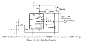
How about a circuit around the good old UA723?
A bit more complex than the ubiquitous a three pin regulator, but that also means you get to have more configuration options.
723 is an ancient chip from early '70, it is very susceptible to RF and can burst into oscillation inside RF field. Me would avoid it, much better chips are available today.
723 is an ancient chip from early 70s....much better chips are available today.
Any recommendations?
Depends on your application.
For 100W AB amplifier output stage: see post #2 from jackinny, last sentence. Beside that, it will sound better with unregulated power supply.
For 100W AB amplifier output stage: see post #2 from jackinny, last sentence. Beside that, it will sound better with unregulated power supply.
Any recommendations?
If you have to use an OEM regulator, consider the LT1963A and LT3015 -- much better sounding than the LM317/337.
....For 100W AB amplifier output stage: see post #2 from jackinny, last sentence. Beside that, it will sound better with unregulated power supply.
I am currently using a AC line regulator. It is a tap-switched autotransformer with +/- 4% regulation. It outputs 110VAC anywhere from 85-130VAC in. Problem is the field noise is beyond comprehension. I had to mount it in a 1/8" thick steel box (inside the chassis) and it's still noisy. Keep in mind my amp is very high gain. A fly landing on some of the input devices can be heard through the speaker. When this device switches nothing can be heard.

The one shown regulates +/- 8% but is cheap. I paid $75 for mine.
One remedy for the field noise is to use two of the internal toroids mounted physically opposed and electrically parallel, so the fields cancel. Shielding would still be needed, but not as much. Weight and expense double; however I get a spare controller board and two original enclosures instead of one. It makes a great project box with a handle, cooling fan, crude AC meters, cable. It is made of sheet steel so is inherently shielded. It keeps transformer fields from getting into the breadboard, especially with enclosed, or dual opposed types.
Ok, but why not MOSFETS for the pass transistors themselves?
Incidentally, there are more SMDs to choose from and they boast very low Rds(on). SMD prototypes are difficult, but here only the pass transistors are to be dealt with.
MOSFET's Can used!!!
Just because a particular MOSFET is designed for switching use Does Not mean it won't still work in a linear fashion just like any other MOSFET!
I was confused about this at one point myself until I had asked an engineer at TI one day and that was exactly what he said to me.
A low RDSon means nothing unless you are designing a switching type of circuit.
Many of the SMD parts that boost about low RSDon also have a low Pd rating and they cannot exceed that rating when operated in a linear mode or else they will go PoooF!!
MOSFET's are great when it come to DC linear circuits because there is no current that flows in the gate and they only require a voltage to set its resistance.
A simple opamp driving a MOSFET or two can control a huge amount of current.
Take a look at some of TI Fet's, I was messing around with a CSD18534KCS in a linear mode directly across a big power supply with just an amp meter hooked in series with it, and I was amazed it the power handling and current it was capable of handling.
And it is one of there littler ones in that series, I have few different ones with Pd's of +180watts to 300watts or so I have all three of the CSD185xxKCS types.
I was so impressed with these that I think they could be an alternative (and cheaper part) to make a decent Aleph Class A amplifier out of them as well.
N-Channel MOSFET Transistor | Products for N-Channel MOSFET Transistor | 44 mosfet battery charger
That is basically what a series pass regulator is anyhow, Class A amplifier only it is run in a DC mode and not AC.
The gate capacitance is the main factor to consider when running a MOSFET in a AC or switching mode but means little in a DC regulator.
jer 🙂
P.S. Thank You Jackinnj for mentioning the LT3015's I had forgotten about those as I had them on my list of things to get, I already have the LT1963's to rebuild in my bench supply.
On the last page of the LT3015 data sheet it shows how to parallel them.
Last edited:
MOSFET's Can used!!!
Just because a particular MOSFET is designed for switching use Does Not mean it won't still work in a linear fashion just like any other MOSFET!
A low RDSon means nothing unless you are designing a switching type of circuit.
Many of the SMD parts that boost about low RSDon also have a low Pd rating and they cannot exceed that rating when operated in a linear mode or else they will go PoooF!! ....jer 🙂....
And that is what we have with the 3-term regulator designs above. They are switching on and off.
But in a Class A amp, the MOSFETs run in the linear region. As such the SMD devices with their low Pd ratings will burn. Besides they are designed to be cooled with the copper traces on the PCB.
For the regulator design in question, we should use the LT regulators with the SMD MOSFETs. Incidentally, any of these regulators are quieter when dropping as much voltage as is feasible, in addition to a small value capacitor in the adjustment circuit. The high voltage drop in relation to noise reduction is mentioned in the LT literature. They don't give switching frequencies, but it needs to be well above 20kHz under any condition. Right?
No, the aforementioned little 3 legged bugz are not switching regulators they are linear regulators.
" Besides they are designed to be cooled with the copper traces on the PCB "
This works to help cool the device but this is not enough if a large Pd is demanded from the device.
When a FET is hard switched full on then it has its lowest RDSon and ohms law with the current flowing through the device will tell you what the required Pd will be, and, when it is switched off well then there is no current flowing and there wont be any amount of significant Pd required from the device because it is off.
Just like a mechanical switch or a relay.
If it is well designed circuit, a switching regulator can be very very quiet, in fact there are some that can actually rival their linear counterparts.
The drawback is that they almost always require more components.
jer 🙂
Last edited:
No, the aforementioned little 3 legged bugz are not switching regulators they are linear regulators....jer 🙂
I assumed there was some kind of switching as I have an LM317 that when adjusted closer to the supply. I guess it was getting close to dropout. I designed the control circuit to run at 12VDC and when it was dropped to 11.85V the noise disappeared. And all the devices were opto-isolators. Yes, it was grounded. I found out what happens when they are not. Bzzzzzzzzzz...
How about this one? $25 shipped:

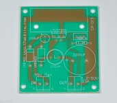
A populated board:

The frequency is fixed well beyond audio band, but RFI is another question. Perhaps I will try one while my high gain amp is still here, to find the shielding requirements.
Here's an enclosed one. Easier to shield:

Attachments
Last edited:
The LM2576 is an interesting regulator I had discovered it a while back in a thread somewhere.
I had been wanting check it out but I have no experience with it.
Frankly I am not a big fan of power switching regulators when it comes to audio circuits, But that is just me.
I don't much care for full range Class d amps either but I think that they are okay for sub use though.
I think that it does have a few limitations but with some more input into the design of the output filtering perhaps it could be made to work well for small chipamps since its current rating is only a maximum of 3 amps.
Again the cost of more parts to reduce noise it creates rather than using a linear regulator that has very little residual noise to begin with.
I could not tell at First glance of the datasheet what the exact minimum current load rating is to maintain a proper output voltage, since all of the graphs start at 300ma. .
Maybe someone whom has more experience with this chip can chime in and fill in the blanks for us.
jer 🙂
....the design of the output filtering.... jer 🙂
Yes, the same is required for a SMPS. The chip boasts "low" ripple. That means it's no good for audio.
Instinctively, I would add either another LC stage or RC just like passive HT supplies to achieve that "flatline". Perhaps a small value series resistor with the local bypass caps on the power amp board would do it. My board was designed overkill in that area: A maximum of 10,000uF per rail. A 1R series resistor would drop 3V at full load and flatten much ripple.
A load resistor would have to be permanent to provide the minimal "quiescent" current.
On second thought, I would not trust those cheapies for genuineness. If an experiment is to be done, better get the bare board and load it with guaranteed quality. I cringe at that inductor and would be worried about the chip itself.
You can make a linear regulator into a switching regulator -- shown in several National Semi application notes.
You can make a linear regulator into a switching regulator -- shown in several National Semi application notes.
Kindly direct; cannot find any.
On page 22 of this app. note shows one version,
https://www.fairchildsemi.com/datasheets/LM/LM7805.pdf
I am sure you can probably find TI's version somewhere in their 100"s of app notes, I have seen it several times but I never made a note of it.
https://www.google.com/search?num=1...1.0....0...1.1.64.serp..3.29.2661.1QVvc11QxN0
jer 🙂
https://www.fairchildsemi.com/datasheets/LM/LM7805.pdf
I am sure you can probably find TI's version somewhere in their 100"s of app notes, I have seen it several times but I never made a note of it.
https://www.google.com/search?num=1...1.0....0...1.1.64.serp..3.29.2661.1QVvc11QxN0
jer 🙂
On page 22 of this app. note shows one version,....jer 🙂
Thanks, I never noticed it. I will have to check to see if the scheme can output 50VDC.
This paper http://www.ti.com/lit/an/snva559/snva559.pdf gives wise counsel applicable to the LM2576HV idea. It appears the bare board in the pic above was designed properly. However, after reading this paper, there is no chance I would acquire a populated board from them. I will pay the extra few bucks.
I am concerned more with the RFI than the ripple.
Last edited:
Kindly direct; cannot find any.
You're not looking very hard:
Attachments
Well, another power amp regulator discussion has bitten the dust.
First, I would like to correct a statement I made about that LM2576HV board. I said it was designed properly, but it is not since there is no star ground.
That aside, the tap-switching autotransformer wins. Here's why:
1. Virtually no wasted power.
2. Does not introduce RFI in audio circuits including high gain (see note below).
3. +/- 4% regulation is sufficient for all applications, thus eliminating the need for subsequent regulation.
4. Good for 100/220VAC and 50/60Hz.
5. Drastically reduces inrush since the autotransformer acts as a series inductor, eliminating the need for a soft-start circuit if one was necessary.
6. Relatively inexpensive (also see note below).
The note:
The big problem is that these types of regulators are designed to be mounted outside the audio chassis.
If one would want it inside, a pair of custom wound toroids would be necessary in addition to steel shielding. The only way this would be economical is to have at least 100 pieces made, i.e., 50 units. Antek in NJ USA would be the place to go first.
A minor problem is obtaining the control boards separately, direct from the manufacturer. That too would require a volume purchase to make it economically feasible, or even possible.
Another minor problem is the control board is fairly large and may present a hassle trying to find a good place for it in a tight chassis. However, it is fairly thin.
An autotransformer ? So you want the means voltage on your circuit !
And auto or not, you still have the same inrush current problem.
Mona
And auto or not, you still have the same inrush current problem.
Mona
....you still have the same inrush current problem.
..Mona
Thanks. I was in error as I thought it was a series inductor. Special autotransformers are made to reduce inrush of motors upon starting, but they do this by drastically reducing start voltage. This is not the case with the line regulator in question, although it automatically starts at the lowest voltage setting for safety.
Anyway, the tap-switcher in question looks like this schematically:

I was wondering why that extra wire was connected to neutral....
I also reconsidered the parallel cost problem. Unless you have money to burn, it would be more economical to find a good deal on two units, and deal with the increased size which is not that much different. I did see one distributor selling 10 pieces and substantial discount. Plus, shipping is somewhat cheaper in quantity.
Thank you for bringing that to my attention.
- Status
- Not open for further replies.
- Home
- Amplifiers
- Power Supplies
- LM317 + 2 Transistors "Class A" Regulator?