Chris, I think the confusion arises because of the conflation of RF applications (where zero-bias class B2 is very common) with audio applications (where AB2 or B2 are rare).
Cnpope:
"Quote:
Originally Posted by Keit
Very early in this thread Koonw showed with his sims that grid current flows...
Yes, but that is based on a particular Spice model for the 6C33C. Other models for the 6C33C disagree with that. The only real arbiter for this question is to do the real-life measurements. "
Which 6c33c spice model? Think we share model with others like PSpice is it?
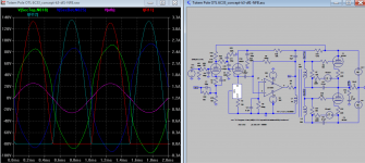
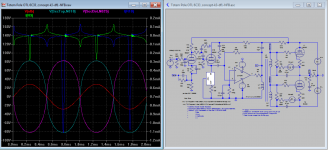
Under this model, here is snapshot shot the result like you have described, but still much heavier grid current spike than before. It appears that "grid current" always there and "grid current spike" which occurs only above zero. Have you guys differential them already? Keit and I are quite concerned about, don't know the others?
"Quote:
Originally Posted by Keit
Very early in this thread Koonw showed with his sims that grid current flows...
Yes, but that is based on a particular Spice model for the 6C33C. Other models for the 6C33C disagree with that. The only real arbiter for this question is to do the real-life measurements. "
Which 6c33c spice model? Think we share model with others like PSpice is it?
Under this model, here is snapshot shot the result like you have described, but still much heavier grid current spike than before. It appears that "grid current" always there and "grid current spike" which occurs only above zero. Have you guys differential them already? Keit and I are quite concerned about, don't know the others?
Attachments
Last edited:
You guys are comparing two different circuits as smoking-amp already pointed out, the different results have nothing to do with the 6C33C model.
You guys are comparing two different circuits as smoking-amp already pointed out, the different results have nothing to do with the 6C33C model.
Not really, I got both circuits..unless like Cnpope said this model is not behaving well. We have recognized the usual one Smoke-amp pointed out. It's fair to say circuit has effects on sim so it's either to look for source of cause or blame the model or what now?
Last edited:
My bad, I thought both of you were using the model that was included in the Mytriode.txt, no?
Code:
**** 6C33 ******************************************
* Created on 10/15/2014 15:29 using paint_kit.jar 2.9
* www.dmitrynizh.com/tubeparams_image.htm
* Plate Curves image file: 6c33.jpg
* Data source link:
*----------------------------------------------------------------------------------
.SUBCKT 6C33C 1 2 3 ; Plate Grid Cathode
+ PARAMS: CCG=30P  CGP=31P CCP=10.5P RGI=1000
+ MU=3.24 KG1=134.3 KP=14.9 KVB=663 VCT=0 EX=1.34
* Vp_MAX=320 Ip_MAX=1000 Vg_step=10 Vg_start=0 Vg_count=13
* Rp=4000 Vg_ac=55 P_max=40 Vg_qui=-48 Vp_qui=300
* X_MIN=65 Y_MIN=152 X_SIZE=413 Y_SIZE=515 FSZ_X=1008 FSZ_Y=769 XYGrid=false
* showLoadLine=n showIp=y isDHT=n isPP=n isAsymPP=n showDissipLimit=y
* showIg1=y gridLevel2=n isInputSnapped=n
* XYProjections=n harmonicPlot=n harmonics=y
*----------------------------------------------------------------------------------
E1 7 0 VALUE={V(1,3)/KP*LOG(1+EXP(KP*(1/MU+(VCT+V(2,3))/SQRT(KVB+V(1,3)*V(1,3)))))}
RE1 7 0 1G  ; TO AVOID FLOATING NODES
G1 1 3 VALUE={(PWR(V(7),EX)+PWRS(V(7),EX))/KG1}
RCP 1 3 1G   ; TO AVOID FLOATING NODES
C1 2 3 {CCG} ; CATHODE-GRID
C2 2 1 {CGP} ; GRID=PLATE
C3 1 3 {CCP} ; CATHODE-PLATE
D3 5 3 DX ; POSITIVE GRID CURRENT
R1 2 5 {RGI} ; POSITIVE GRID CURRENT
.MODEL DX D(IS=1N RS=1 CJO=10PF TT=1N)
.ENDSYes I use same model throughout (can check the snapshot). I will check how other 6c33c model behaves.
**** 6C33 ******************************************
* Created on 10/15/2014 15:29 using paint_kit.jar 2.9
* Model Paint Tools: Trace Tube Parameters over Plate Curves, Interactively
* Plate Curves image file: 6c33.jpg
* Data source link:
*--------------------------
**** 6C33 ******************************************
* Created on 10/15/2014 15:29 using paint_kit.jar 2.9
* Model Paint Tools: Trace Tube Parameters over Plate Curves, Interactively
* Plate Curves image file: 6c33.jpg
* Data source link:
*--------------------------
Who knows what SPICE models have been used? That is part of the problem. I calculated off the published curves in the 6C33C datasheet.Yes, but that is based on a particular Spice model for the 6C33C. Other models for the 6C33C disagree with that. The only real arbiter for this question is to do the real-life measurements.
I've said this before: I wish I had a dollar for every newbie misled by dodgy SPICE runs. I would be quite rich.
It isn't really. A competently designed Class A amp will soft clip on both positive signal peaks (anode going low), and on negative signal peaks (grid getting near cut-off where there is a change in curvature) simultaneously. This will mean a standing current such that on clipping negative peaks there will still be quite a bit of anode current. Also, the grid bias will be significantly above half the signal grid swing at clipping.Well, to quote the definition you gave earlier in the thread, "A Class A amplifier is an amplifier in which the grid bias and alternating grid voltages are such that the plate current of the output valve or valves flows at all times." So what qualifies as "plate current flowing at all times"? A minimum pltae current of 0.5A presumably qualifies. But what about 50mA? Or 1mA? Or 1 nanoamp? Obviously somewhere between 0.5A and 1 nanoamp, one has to draw a line. But that means that a somewhat arbitrary, and hence potentially contentious, line is being drawn.
More importantly, what has been debated by BallPencil here is not what is Class A, but what is Class AB as distinct from Class B. If you check the standard definitions, it is still quite clear. It's only not so clear if you don't see why the various classes have been defined.
it sounded to me as if you were saying that you want some other factor, other than onset of grid current, to be the defining one that sets the "maximum power" of the amplifier.
In any competently designed amplifier, it WILL be clipping that sets the maximium output. It is a real limit, set by the circuit.
Grid current is not a power limit. The user can, and will if grid current starts before clipping, turn it up past the grid current point, because the resulting distortion will not be continually evident.
No, there is no Law that says the user must. But that is what he/she will do.There is no obligation to crank up the volume so high that grid conduction occurs.
Why would you build an amplifer capable of X watts and then decide not to use anywhere near X watts anyway? It's not as though correcting the faults is going to cost BallPencil any money.
Last edited:
*
* Generic triode model: 6C33CB
* Copyright 2003--2008 by Ayumi Nakabayashi, All rights reserved.
* Version 3.10, Generated on Sat Mar 8 22:39:32 2008
* Plate
* | Grid
* | | Cathode
* | | |
.SUBCKT 6C33C A G K
BGG GG 0 V=V(G,K)+1
BM1 M1 0 V=(0.31995431*(URAMP(V(A,K))+1e-10))**-1.9846926
BM2 M2 0 V=(0.43045404*(URAMP(V(GG)+URAMP(V(A,K))/1.7800853)+1e-10))**3.4846926
BP P 0 V=0.015432878*(URAMP(V(GG)+URAMP(V(A,K))/4.1353667)+1e-10)**1.5
BIK IK 0 V=U(V(GG))*V(P)+(1-U(V(GG)))*0.026902304*V(M1)*V(M2)
BIG IG 0 V=0.0077164388*URAMP(V(G,K))**1.5*(URAMP(V(G,K))/(URAMP(V(A,K))+URAMP(V(G,K)))*1.2+0.4)
BIAK A K I=URAMP(V(IK,IG)-URAMP(V(IK,IG)-(0.013640208*URAMP(V(A,K))**1.5)))+1e-10*V(A,K)
BIGK G K I=V(IG)
* CAPS
CGA G A 31p
CGK G K 30p
CAK A K 10.5p
.ENDS
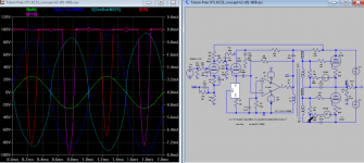
The result (close, only input differ by 0.1V = 3.1-3.0) from another model from our diyaudio link. Try another model? Any one got any model? Edit: I accidentally alter the bottom bias to -79 hence the lower bottom spike waveform. The 2nd one shows the right bias. I note the bias effect on spike size: does it means more -neg bias less spike? Yes it appears so, see spike for -80V on the left.
* Generic triode model: 6C33CB
* Copyright 2003--2008 by Ayumi Nakabayashi, All rights reserved.
* Version 3.10, Generated on Sat Mar 8 22:39:32 2008
* Plate
* | Grid
* | | Cathode
* | | |
.SUBCKT 6C33C A G K
BGG GG 0 V=V(G,K)+1
BM1 M1 0 V=(0.31995431*(URAMP(V(A,K))+1e-10))**-1.9846926
BM2 M2 0 V=(0.43045404*(URAMP(V(GG)+URAMP(V(A,K))/1.7800853)+1e-10))**3.4846926
BP P 0 V=0.015432878*(URAMP(V(GG)+URAMP(V(A,K))/4.1353667)+1e-10)**1.5
BIK IK 0 V=U(V(GG))*V(P)+(1-U(V(GG)))*0.026902304*V(M1)*V(M2)
BIG IG 0 V=0.0077164388*URAMP(V(G,K))**1.5*(URAMP(V(G,K))/(URAMP(V(A,K))+URAMP(V(G,K)))*1.2+0.4)
BIAK A K I=URAMP(V(IK,IG)-URAMP(V(IK,IG)-(0.013640208*URAMP(V(A,K))**1.5)))+1e-10*V(A,K)
BIGK G K I=V(IG)
* CAPS
CGA G A 31p
CGK G K 30p
CAK A K 10.5p
.ENDS
The result (close, only input differ by 0.1V = 3.1-3.0) from another model from our diyaudio link. Try another model? Any one got any model? Edit: I accidentally alter the bottom bias to -79 hence the lower bottom spike waveform. The 2nd one shows the right bias. I note the bias effect on spike size: does it means more -neg bias less spike? Yes it appears so, see spike for -80V on the left.
Attachments
Last edited:
Agreed. And there is no compelling evidence that any 6C33C model being used in Spice is especially trustworthy in this "off-piste" territory when the anode current is of order 2 or 3 amps. But since you were invoking the results that koonw obtained using a Spice simulation, I just wanted to remark that other 6C33C models appear to give somewhat different results. Certainly, in the one I am using, Vgk is still negative when the anode current is 2.5A. I think that is different from the conclusion in the model koonw is using?Who knows what SPICE models have been used? That is part of the problem.
I calculated off the published curves in the 6C33C datasheet.
Well again, there is room for considerable uncertainty, I think, when trying to extrapolate "off-piste" from the usual published curves. The only thing that can, I think, really be trusted is some actual measurements. For what it's worth (and who knows how Sanei Radio obtained the extended curve for Vgk= -2V), that plot jazbo8 posted in #193, seems to show that at Vgk= -2V the anode current is around 3A, I suppose.
As I said, there is quite a lot of vagueness in such a definition. How exactly does one interpret "quite a bit" of anode current? 0.5A? 100mA? 10mA?....It isn't really. A competently designed Class A amp will soft clip on both positive signal peaks (anode going low), and on negative signal peaks (grid getting near cut-off where there is a change in curvature) simultaneously. This will mean a standing current such that on clipping negative peaks there will still be quite a bit of anode current.
And actually, I think one manufacturer of OTL amplifiers has asserted that it has class A operation, even though the minimum anode current is pretty low. And these things do then get debated rather heatedly!
Well, I was responding to ballpencil's post #190, where he raised questions about class A operation.More importantly, what has been debated by BallPencil here is not what is Class A, but what is Class AB as distinct from Class B.
Chris
I already covered that in apost long ago. Perhaps you didn't notice it as you cam in late.Well again, there is room for considerable uncertainty, I think, when trying to extrapolate "off-piste" from the usual published curves.
While it is gnerally regarded as unwise to extraplote, one can ask which way is likely to bend? Toward more postive grid voltage than the extrapolateed value to get 2,5A, or less postive? I'm putting my money on the former.
I already agreed with that.The only thing that can, I think, really be trusted is some actual measurements.
I used the geniune Russian manufacturer curves.For what it's worth (and who knows how Sanei Radio obtained the extended curve for Vgk= -2V
I thought I had explained this multiple times. It doesn't matter what the exact current is. You are asking the wrong question.As I said, there is quite a lot of vagueness in such a definition. How exactly does one interpret "quite a bit" of anode current? 0.5A? 100mA? 10mA?....
The health industry has a definition of obese. It a ratio of mass to square root of height. But a very fit boxer or weightlifter would not be treated by doctors as obese even though his ratio may welll be quite a bit higher than some short unfit couch potato they do treat as obese.
If it looks like Class B (tube conduct about half a cycle), feels like Class B (distortion - high and completely dependent on tube matching), and smells like Class B (draws grid current), eats like Class B (HT drain proportional to signal), its' Class B. Idle curent doesn't matter much.
Doesn't matter. Ethics vary. Its better marketing-wise if you say the thing is AB and not B. B is public address stuff.And actually, I think one manufacturer of OTL amplifiers has asserted that it has class A operation, even though the minimum anode current is pretty low. And these things do then get debated rather heatedly!
In any case you can indeed have AB1 or A in OTL. Just not with the tubes, tube count, and loudspeaker BallPencil chose.
Remember when the compact cassette became popular in the early 1970's? Most of the Japanese cassette deck manufacturers claimed signal to noise as good as open reel. Nakamichi was an exception - their spec were accurate and their descks had special technology. But they didn't aim at the reatil market. With such narrow tracks and 1-7/8th speed reel-to-eel performance was not possible. I recall a hi-fi dealer I knew who would not seel a cassette deck to Dept of Civil Aviation technicians. The had a tendecy to test their purchase with instruments - they could/t pass. The average non-technical user just enjoyed the music.
Last edited:
Cnpope said:
"Certainly, in the one I am using, Vgk is still negative when the anode current is 2.5A. I think that is different from the conclusion in the model koonw is using?"
Every model is different but the differences can not be more than the actual tube you're going to use, you know what I mean. 🙂. The persons who generates the model use tube parameter from different year and site. I can see 0 volt I is 2.2A/2.7A then similar differences I peak. Look within the tolerance , that best we can hope for.
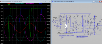
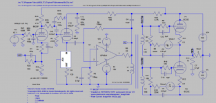
Here is the latest version 1) Select the spice model by comment off spice directive 2) If you want to change the drive level, just change the OpAmp supply up 20V-30V. This latest model on grid drive, I check the frequency response looks good, hope you like it and report any issues you may have.
Attachments
Last edited:
Really? Extrapolate the zero bias line on the published anode curves up to 2.5 amp and see where it lies - it lies to the left of 130V anode voltage. Hence postive grid voltage required.
Assuming of course the the tube can actually deliver 2.5 amp over a period of time. That's well outside ratings. I have my doubts. Over time its' likely to need increasingly more positive grid volts.
Apologies for reviving this thread, but I have now finally returned to the same side of the ocean as my OTL amplifiers, and I've had a few minutes to spare to makes some measurements. In particular, I've been able to look at the anode current as a function of the grid-to-cathode voltage, for the 6C33C. I did this by putting a scope between cathode and grid, and looking at Vgk at the peak of the waveform when driving the amplifier with a sinewave, and measuring also the corresponding rms voltage across an 8ohm resistive load. Simple algebra then gives the plate current at the peak. Doing this for different amplitudes of the sinewave allowed me to determine the plate current Ip as a function of Vgk. The measurements are a bit rough and ready, but not too bad, I think. Here is what I got:
Vgk . . Ip
-30 . . 0.68
-20 . . 1.17
-10 . . 1.75
-5 . . 2.15
-4 . . 2.26
-3 . . 2.30
-2 . . 2.40
-1 . . 2.45
0 . . 2.56
(Sorry about the ".." between the numbers on each line. I found if I didn't put something there, the spaces I tried putting were ignored when the message formatted.)
I should add that these results are slightly "skewed" relative to a standard Ip vs Vgk plot, because the plate-cathode voltage gets somewhat lower (in a calculable way) as the plate current rises. This is because the supply rails in my amplifier are +166V and -166V, but the actual plate-cathode voltage for each measurement above will be 166V minus the voltage dropped across the 8ohm load resistor. (So, down to about 145V plate-cathode voltage by the time the current reaches 2.56A.)
So, the upshot is that indeed the 6C33C can pass 2.5A with non-positive grid voltage. And by staying in the region with a few volts (negative) on the grid, the plate current can still exceed 2A. In my amplifier the onset of clipping comes at almost exactly the 25W rms mark, which means that it is just about when the maximum plate current is 2.5A. I wouldn't be surprised if the clipping I am seeing is occurring precisely because the 6C33C is starting to pass grid current.
It seems to me that the conclusion is that one can get something of order 20 to 25W out of a pair of 6C33C tubes in an OTL without having to worry at all about grid current; it is just a non-issue. And I don't think one would be wanting to try to push into the region where the plate current was getting to be significantly more than 2.5A in any case.
In practice, 6C33C OTLs with capacitor coupling to the output stage, such as the design by Hans Beijner, seem perfectly capable of producing up to around 25W into 8ohms without any sign of grid current becoming an issue to worry about.
Chris
Last edited:
Have you or has anyone compared the actual data with sim data? If not I can do it (later).
"Vgk . . Ip
-30 . . 0.68
-20 . . 1.17
-10 . . 1.75
-5 . . 2.15
-4 . . 2.26
-3 . . 2.30
-2 . . 2.40
-1 . . 2.45
0 . . 2.56?"
"Vgk . . Ip
-30 . . 0.68
-20 . . 1.17
-10 . . 1.75
-5 . . 2.15
-4 . . 2.26
-3 . . 2.30
-2 . . 2.40
-1 . . 2.45
0 . . 2.56?"
Have you or has anyone compared the actual data with sim data? If not I can do it (later).
"Vgk . . Ip
-30 . . 0.68
-20 . . 1.17
-10 . . 1.75
-5 . . 2.15
-4 . . 2.26
-3 . . 2.30
-2 . . 2.40
-1 . . 2.45
0 . . 2.56?"
I just tried using my 6633C sim in SPICE. With the same conditions (166V supply, in series with 8 ohms), I get
Vgk .. Ip
-30 .. 0.89
-20 .. 1.35
-10 .. 1.99
-5 .. 2.57
-4 .. 2.72
-3 .. 2.87
-2 .. 3.04
-1 .. 3.23
0 .. 3.43
So the 6C33C model I am using in SPICE tends to exaggerate the plate current for a given Vgk, in comparison to the real-life sample I looked at. I'm sure other models will give different results since, after all, these are at operating points that are pushed well beyond the normal range.
Also, I only looked at one example tube. I could have tried the other one in the totem pole, but that would have required floating my rather aged oscilloscope at -166V, and I'm not inclined to do that! More realistically, I could try the upper tube in the other channel of the amplifier. Unfortunately I restored the amplifier to my living room having done the measurements earlier, so I'll probably have to postpone further experimentation for a few days.
Chris
Fairly close, up to -3V, for the rest due your supply volt dropped maybe you also reduce the sim supply volt down to 140V at zero bias, instead of 166V? Please confirm just the last one.
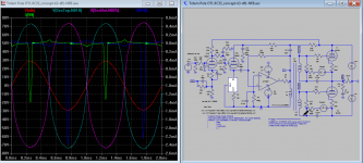
There you go..
Easier to compare.
Easier to compare.
An externally hosted image should be here but it was not working when we last tested it.
Fairly close, up to -3V, for the rest due your supply volt dropped maybe you also reduce the sim supply volt down to 140V at zero bias, instead of 166V? Please confirm just the last one.
In my sim, the supply voltage was always fixed at 166V. The 8 ohm resistor in series means that the anode to cathode voltage is 166 minus the product of the anode current times 8 ohms--just like in my actual measurements. Of course, my supply voltage could have been dropping a bit too, at high current, since it's not ideal, unlike in the sim.
Ballpencil's 6C33C model seems a little closer to what I found with measurements than my sim is.
Chris
I just tried using my 6633C sim in SPICE. With the same conditions (166V supply, in series with 8 ohms), I get
Vgk .. Ip
-30 .. 0.89
-20 .. 1.35
-10 .. 1.99
-5 .. 2.57
-4 .. 2.72
-3 .. 2.87
-2 .. 3.04
-1 .. 3.23
0 .. 3.43
So the 6C33C model I am using in SPICE tends to exaggerate the plate current for a given Vgk, in comparison to the real-life sample I looked at. I'm sure other models will give different results since, after all, these are at operating points that are pushed well beyond the normal range.
I think I have tried every spice model available for 6C33C, most are really bad, the best one I found is from Excem, a french research institute, it is the only one I found that include compensation for the kink at low anode currents. This kink doesn't show on most other triodes so most standard models will give wrong results which affect prediction of distortion. Most 6C33C I have measured can sink 2.5A at about 130V anode voltage at 0 V on grid, the tubes in my first OTL was used like that for more than 10 years and still gave the same output power.
Well designed OTLs survive because average current is not very high when playing music, even at full volume, it would be a different thing if the amplifier was constantly giving full power, I have done full power tests for 24 hours which the tubes survived but everything was very hot of course.
- Status
- Not open for further replies.
- Home
- Amplifiers
- Tubes / Valves
- Another Approach to Totem Pole OTL Amplifier