lets see the plots in a real audio electronics application, or do the numbers
pointing to physics demos really doesn't tell us if its ever audible in magnetic materials we actually use, or if it is avoided by something you can do easily or even need to do for other reasons
like shorting rings
and again how do transformers ever work in audio - you know like the moving coil step ups?
apparently you can now demo General Relativity in a lab with current generation benchtop clocks by just putting one on a lab jack
http://www.wired.com/2010/09/ordinary-relativity/
Last edited:
the coil and not so special iron rod is built to demonstrate an obscure effect ( I wouldn't use such a core for an XO for a number of reasons , heck they couldn't even bother getting rid of the hum LOL ). BTW there are so many new formulations of ferrites, powdered iron, and steel laminations designed for high power which can have side applications for audio. Like everything else they have to be thoughtfully designed fit for purpose. E.g. Don't buy any old ferrite bobbin made from iron filings and glue and start winding
Can anyone summarize the results of the tests referenced to in post 38? I still think that distortion and modulation effects due to core nonlinearity dominate over other deviations from ideal behavior, but I have never seen any quantitative assessment.
Can anyone confirm:
A rod/bar of ferrous core material is equivalent to a core with a BIG air gap, i.e. it is not a ring/circuit of continuous ferrous core.
A rod/bar of ferrous core material is equivalent to a core with a BIG air gap, i.e. it is not a ring/circuit of continuous ferrous core.
Does it follow that the air gap prevents the core from saturating?
How do we define the maximum current that can be passed through the coil of a rod type cored inductor?
How do we define the maximum current that can be passed through the coil of a rod type cored inductor?
toroid core
I have implied with good results a toroid core on my cross over , but is very important
know exact maximum values of the power .
The core well working nearest zero on the BxH plane (big core for strong current).
I use the toroid cores only for components not in series off the woofer 🙄
I have implied with good results a toroid core on my cross over , but is very important
know exact maximum values of the power .
The core well working nearest zero on the BxH plane (big core for strong current).
I use the toroid cores only for components not in series off the woofer 🙄
Correct. The rods, bars, mushrooms and bobbins typically used for audio applications form a magnetic circuit that includes a lot of air, there is no possibility for a field line to stay inside the core entirely.A rod/bar of ferrous core material is equivalent to a core with a BIG air gap, i.e. it is not a ring/circuit of continuous ferrous core.
Yes and no. The air gap has the effect of reducing the apparent permeability of the core. Permeability is the amount of magnetization the core material undergoes in response to an applied magnetic field (which is proportional to the current through the windings). The relative permeability of any material is the ratio of its permeability to that of vacuum. Air is very close to one (so its absolute permeability is very close to that of vacuum), so for most practical purposes it is entirely ignored. So if an air gap is present, the amount of magnetization the core undergoes in response to a current through the windings is reduced. The larger the air gap, the less the core will become magnetized at a given current. But it is always possible to increase the current through the windings until the core becomes fully saturated, i.e. all magnetic domains in the core material are aligned. Adding an air gap has the effect of increasing the current at which a given level of saturation is reached, all other things remaining equal.Does it follow that the air gap prevents the core from saturating?
When an air gap is added to an inductor, the self inductance decreases, the saturation current increases and the amount of energy that the inductor can store increases as well. Vacuum/air is hard to magnetize, so it requires a lot of energy to build up a certain field strength. Ferromagnetic materials are very easy to magnetize, and thus require only little energy to be magnetized to the same field strength. The air gap in a gapped core thus stores the bulk of the total energy stored by the inductor.
Now, the B-H relationship of air (which is the magnetic response of a material to an applied magnetic field) is a straight line. The B-H response of ferromagnetics is not, it is S-shaped and exhibits hysteresis. So a core without an air gap will yield a rather non-linear inductor, which is something you don't want in audio filter applications. Gapping the core will lead to most of the energy being stored in the air gap (of linear behavior), and only a small part of the total stored energy in the core (of non-linear behavior). So a gapped core will behave more like a linear inductor than an ungapped core, and it becomes better as the air gap increases in size. This explains why the core geometries of audio inductors are what they are.
It depends on the application. While a small boost converter may function adequately if the inductance of the boost inductor varies by as much as 20% during a cycle, such a variation is totally unacceptable in a filter.How do we define the maximum current that can be passed through the coil of a rod type cored inductor?
It is important not to think of saturation as a point on a curve, but as a process. It starts as soon as the core becomes magnetized, and as the core is magnetized further, its effects become more pronounced. The "saturation point" in your particular application is the point where you decide that the changes in the inductor's properties start to become excessive. So this question can't be answered here definitively.
In case of a loudspeaker filter inductor, you could for example specify the AC current at which a specified amount of distortion is generated by the inductor.
Last edited:
And in case of the most of us mere mortals, this is a very reliable approach. That has led to thousands of good quality designs in filtering.In case of a loudspeaker filter inductor, you could for example specify the AC current at which a specified amount of distortion is generated by the inductor.
BTW one could argue for two-tone distortion measurements, but as most quality inductors have distortion specs way better than the loudspeaker systems they're used in, I wouldn't bother.
Do you have a source of these specs? I find the data on most (if not all) crossover inductors to be sorely lacking here.most quality inductors have distortion specs way better than the loudspeaker systems they're used in
There are very few distortion results for speakers emitting 60dB, or 70dB, of SPL @ 1m.
Most that show distortion do so for >=90dB of SPL @ 1m
Most that show distortion do so for >=90dB of SPL @ 1m
Yes, it is a German DIY loudspeaker magazine. I have those issues somewhere in the attic (but they refuse to make an appearance all by themselves). From memory:Hi Sonce
do we have to buy something to get access?
did they test laminated steel cores ( what I use )
Laminated I cores are the best, followed by the E cores.
The worst are EI cores, which I learned the hard way earlier, by buying a pair of EI core inductors Monacor LSI-22T. They exhibit almost 1% distortion from the 3th harmonic alone with only 1A current (test in Hobby Hi-Fi magazine, issue 6-2008), but the Isat saturation current (producing 3% 3th harmonic) is correctly stated at 7.9A in the Monacor specification:
http://www.monacor.de/pdf/produkte/detailseite.php?artikelid=2213&lang=1
Define 'sorely lacking' please 😉 . Anyhow, Elektor Magazine published some measurements back in 1988 and I tend to trust the measurements published in the aforementioned Hobby Hifi magazine (results are not that far apart too).Do you have a source of these specs? I find the data on most (if not all) crossover inductors to be sorely lacking here.
As to distortion of loudspeakers: in my (humble) opinion currents of 1A drive a lot of loudspeaker systems already to rather big distortion figures. These may be caused by inductors in the filter section, but far more likely by the driver units.
Back in 1988 I was 10 years old during most of the year, so forgive me for not having noticed this publication. 😉
Also IMHO the first party responsible for publishing complete product data is the manufacturer of the product. Most products are properly documented by the manufacturer, with the exception of filter components.
Distortion at low levels might also come from core hysteresis, so I wouldn't be a bit surprised if there is actually an optimum power level at which distortion is minimal (in case of the EI cored inductors), above and below which distortion is higher. At very low levels, it may even cause an upwards deviation from the stated inductance. I only know the Dutch word for it ("aanvangszelfinductie"), perhaps someone can help out by bringing in the correct English term. This is typical behavior for iron cores.
Probably initial inductance, as opposed to incremental inductance and amplitude inductanceI only know the Dutch word for it ("aanvangszelfinductie"), perhaps someone can help out by bringing in the correct English term.
And in case of the most of us mere mortals, this is a very reliable approach. That has led to thousands of good quality designs in filtering.
BTW one could argue for two-tone distortion measurements, but as most quality inductors have distortion specs way better than the loudspeaker systems they're used in, I wouldn't bother.
You could, and I did that on one inductor to satisfy my curiosity. It was a question brought up by someone critiquing my DIYRM-A design. Here's the post I put in that thread:
"So I got into a bit of a debate/question answer session over PM regarding the number of components in the crossover. One of the concerns was that there was no way that a crossover with this many components would be "linear".
By definition a system with linear components, no matter how many there are is still a linear system. This is a pretty fundamental tenant of electrical engineering rigorously supported by a bunch of mathematics I vaguely remember knowing at one point in my life.
Physical components will always have some amount of non-linearity caused by a junction of dissimilar metals, hysteresis of materials etc. In the DIYRM-A crossover the single most suspect component is the 1.5mH laminated core inductor. The lamination will suffer from both hysteresis and saturation resulting in some amount of distortion.
I can't actually remember seeing if someone has ever tested an iron-core inductor for distortion under multi-tone conditions, so I thought I'd give it a shot.
*NOTE: I did this test using the FFT function of an oscilloscope...which has either an 8-bit or 10-bit front end...I will need to re-do this test with a device with enough resolution to actually measure the distortion induced, since this setup did not have enough capability to actually measure the distortion. That said...(spoiler alert) the distortion was lower than I expected.
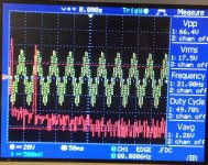
So I set up a circuit with a 5mH ERSE air core inductor from the same line as the 1.5mH used in the DIYRM-A, in series with a 4 ohm resistor. I used my Carver TFM-25 amplifier to put a two-tone test signal, total signal amplitude of 17.5VRMS across the resistor of 20Hz and 200Hz, equal magnitude.
The 17.5VRMS across the resistor equates to 4.375ARMS. Into an 8 ohm load that current equals 153 Watts continuous power.
That's a lot for a speaker intended for nearfield use.
No...that's a $%#@$ lot of power for a speaker intended for nearfield use. Well more than you should ever put into a 6" woofer you're sitting within 1-10 of.
Under test I could feel the inductor core vibrating due to magnetostriction, or the property of magnetic materials to change shape under a strong magnetic field.
No single harmonic of the 200Hz or 20 Hz signal came within 40dB of the applied signals. 40dB down is 1% distortion...please trust that at these signal levels the woofer will show well higher than 1% distortion...as will nearly every 6" woofer.
So...in summary, I have even less concerns regarding using a iron core inductor than I did before. To get the equivalent series resistance in an air core part would require a large inductor that would cut into the interior volume of the speaker and be tough to fit on that back panel.
Attached picture of the oscilloscope screen during testing."
Attachments
Most recent DSO are only 8bit, even the lecroy wavejet 334a (~£5000 rrp)
Its expensive to find a good bandwidth DSO with 12 bit front end, although it depends what you expect of your scope.
Its expensive to find a good bandwidth DSO with 12 bit front end, although it depends what you expect of your scope.
Most recent DSO are only 8bit, even the lecroy wavejet 334a (~£5000 rrp)
Its expensive to find a good bandwidth DSO with 12 bit front end, although it depends what you expect of your scope.
It wouldn't be a scope, it'd be some National Instruments DAQ board, lower sample rate much higher resolution. Likely a 24bit 150kHz ...ish... capture. Effective bits is lower, but much better than the cheap DSO.
Scott
That, combined with the knowledge we're dealing with AC, brings funny thoughts to me. But I remember a recent discussion on our local DIY-forum about Janzen toroidal inductors that show a strong level- and frequency-dependent behavior on their nominal value. So even respected manufacturers will sometimes f%^&up.Distortion at low levels might also come from core hysteresis, so I wouldn't be a bit surprised if there is actually an optimum power level at which distortion is minimal (in case of the EI cored inductors), above and below which distortion is higher.
- Status
- Not open for further replies.
- Home
- Loudspeakers
- Multi-Way
- Ferrite core instead of air core