I have two Thorens 125 MK1 that are not working! Help me please to indentify the broken part on the PCB. I checked everything many times. Each part is working but the whole pcb don't work! How could it be?
I know that the problem is on the control board. I tried the motor and the transformer on the other working example of the 125 thorens. The are working very well!
What is done:
1. All electrolitics caps are changed
2. Switch is cleaned
3. All resistors are checked by the voltmter. They are at specs.
4. Lamp is working.
5. All transistors are checked by be voltmeter. There is no cuircut or short.
6. Other capacitors are checked. They are also fine.
7. Diode bridge checked. Working.
It's absolutely crazy. What should I do with these!

AC on the motor pots give me only 0.6V. While it should be 8, 5 or 2.5V.
How could I find the problem? What to start with?
Hope there could be find some gurus.
Also help me please to check the voltages that are printed on the PCB. Where should I put the voltmeter probes? Check AC or DC?
I know that the problem is on the control board. I tried the motor and the transformer on the other working example of the 125 thorens. The are working very well!
What is done:
1. All electrolitics caps are changed
2. Switch is cleaned
3. All resistors are checked by the voltmter. They are at specs.
4. Lamp is working.
5. All transistors are checked by be voltmeter. There is no cuircut or short.
6. Other capacitors are checked. They are also fine.
7. Diode bridge checked. Working.
It's absolutely crazy. What should I do with these!
AC on the motor pots give me only 0.6V. While it should be 8, 5 or 2.5V.
How could I find the problem? What to start with?
Hope there could be find some gurus.
Also help me please to check the voltages that are printed on the PCB. Where should I put the voltmeter probes? Check AC or DC?
Attachments
I have two Thorens 125 MK1 that are not working! Help me please to indentify the broken part on the PCB. I checked everything many times. Each part is working but the whole pcb don't work! How could it be?
I know that the problem is on the control board. I tried the motor and the transformer on the other working example of the 125 thorens. The are working very well!
What is done:
1. All electrolitics caps are changed
2. Switch is cleaned
3. All resistors are checked by the voltmter. They are at specs.
4. Lamp is working.
5. All transistors are checked by be voltmeter. There is no cuircut or short.
6. Other capacitors are checked. They are also fine.
7. Diode bridge checked. Working.
It's absolutely crazy. What should I do with these!
AC on the motor pots give me only 0.6V. While it should be 8, 5 or 2.5V.
How could I find the problem? What to start with?
Hope there could be find some gurus.
Also help me please to check the voltages that are printed on the PCB. Where should I put the voltmeter probes? Check AC or DC?
Before you made the revision caps.etc was he working ok ?
You have a very old version with two diode bridge in it later version had one.You can measure against the ground on the black motor wire , + en - about 15volt dc on the elco's 2500UF .
About 1 volt base T1 ,1,2v emitter diff.amp T4-T5 about 0,8V emitter.
Switch correct mounted ?
Volken
Before you made the revision caps.etc was he working ok ? Volken
That has to be the number one question.
(terrom... checking transistors and diodes on a DVM isn't definitive proof they are OK)
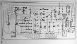
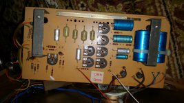
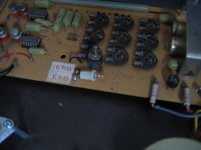
Lets start with the 1 diode bridge 125 mk1 version. Here the photo:
I put a probes to a motor's black pot and 2200uf ecap:
1st gives me 21.8V
2nd gives me 12,7V
I changes all the ecaps as they were very old and seem to be damaged. The motor didnt work before and after the change of them.
What is next?
I put a probes to a motor's black pot and 2200uf ecap:
1st gives me 21.8V
2nd gives me 12,7V
I changes all the ecaps as they were very old and seem to be damaged. The motor didnt work before and after the change of them.
What is next?
Attachments
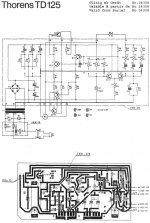
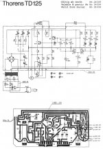
here the schema
here the link dor the pdf
http://www.vinylengine.com/ve_downloads/index.php?thorens/thorens_td125service.pdf
here the link dor the pdf
http://www.vinylengine.com/ve_downloads/index.php?thorens/thorens_td125service.pdf
Attachments
Last edited:
When I checked the transistors by my multimeter there is one strange thing.
If I check the voltages on T4 transistr in diode mode on the DVM I have
0,8V if put red probe on the base and black probe on the emmiter and
0,08V if put red probe on the base and black probe on the collector.
When I desolder this transistor it was 0.8V both! on the pcb the was the other story. The same story is also on the diode bridge. One diode give me 10X less voltage while it's good if I desolder it and check it by the DVM.
I'll have more time tomorrow if you are still stuck but things to check would be the two 0.3 ohm resistors R9 and R10. The AD149 devices are germanium and these will read very differently when checked on a meter.
The circuitry to the right of the diagram is a wein bridge oscillator of sorts. Even if you had a problem with one speed, the other should still work and so that leaves just the amplifier stage as the common denominator.
I think C2 and C3 should have about the same voltage across them, so check that.
Cap C7. That might be worth checking for leakage with one end disconnected to isolate it. Use a high ohms range to test.
R9 I think should have around half the total supply on it. So if the supply is 24 volts then R9 should have around 12 volts on it.
All the base/emitter junctions should have around 0.6 volts across them. Check carefully. The AD149's will be lower at around 0.15 volts. Check.
(I've never seen this circuit before but if your still having no luck then I'll take a closer look tomorrow)
You can't check any parts reliably in circuit but I wouldn't advise desoldering them all just to test. Try and find the fault by careful measurement first. Check the voltage across (you must measure across and not measure to) those base emitter junctions with it all power up and 'working'.
The bulb in the oscillator is worth checking. Don't blow it, just check it on the low ohms range or diode range on your meter and make sure it reads low resistance (not open circuit).
The bulb in the oscillator is worth checking. Don't blow it, just check it on the low ohms range or diode range on your meter and make sure it reads low resistance (not open circuit).
How could I test them across? Could you please write me where to put red (+) and black (-) probe of the DVM?
Do you mean the bulb is bright when its powered up normally ? We are talking about the bulb that connects to T4.
If so then that sounds a bit strange as the bulb is used a thermistor to stabilise the oscillator output and would normally (in most oscillators of this type) not even be visibly lit.
Does the bulb light brightly in the working example ? If not then check/replace T4 and T5 on your faulty board.
To measure the base/emitter voltage you put one meter lead on the base and the other on the emitter. You should never see a voltage more than about 0.6 to 0.7 volts (much lower for the AD149's)
Buld is working as it lights very bright!
Thats not ok its lighting should be not bright .
Most times one off the drivers our outputtransistors are defect .
Not quite following you on that 🙂
What does the good turntable bulb do ? bright or dim ?
and what does the faulty board do ? bright or dim ?
What does the good turntable bulb do ? bright or dim ?
and what does the faulty board do ? bright or dim ?
Not quite following you on that 🙂
What does the good turntable bulb do ? bright or dim ?
and what does the faulty board do ? bright or dim ?
Translation problem not to bright , little bit glowing.
Translation problem not to bright , little bit glowing.
Attachments
That looks OK 🙂
Now put your black meter lead on the negative end of C2 and measure the DC voltage on R9. What is it ?
And on R10. What is it ?
Now put your black meter lead on the negative end of C2 and measure the DC voltage on R9. What is it ?
And on R10. What is it ?
1. Accros the buld is 4,7V DC and it's makes more light than the bulb in the working PCB.
2. Accros the T4 base-emmiter is 5,3V DC base-collector 7,4V DC
3. Negative end of C2 and the DC voltage on R9 - 34V DC
4. Negative end of C2 and the DC voltage on R10 - 32V DC
What next? Is it a good numbers?
2. Accros the T4 base-emmiter is 5,3V DC base-collector 7,4V DC
3. Negative end of C2 and the DC voltage on R9 - 34V DC
4. Negative end of C2 and the DC voltage on R10 - 32V DC
What next? Is it a good numbers?
Not good numbers 😉
Have another measure on T4 but I don't think the problem is there. With the red meter lead on the base and the black on the emitter what polarity is the voltage you measure ? Minus 5.3 means the transistor is reverse biased.
We need to 'prove' the output stage one step at a time.
Switch off and remove TR1 and then connect the black meter lead to negative end of C2 and the red lead to R9 as you did before. Has the 34 volts on R9 now fallen to near zero ?
- Status
- Not open for further replies.
- Home
- Source & Line
- Analogue Source
- Thorens 125 MK1. Help me please repair this PCB.