Hi
I have Systemdek IV electronic that I have returned to after 10 years, it failed then and I stored it away.
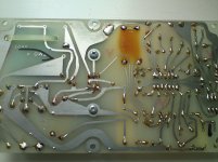
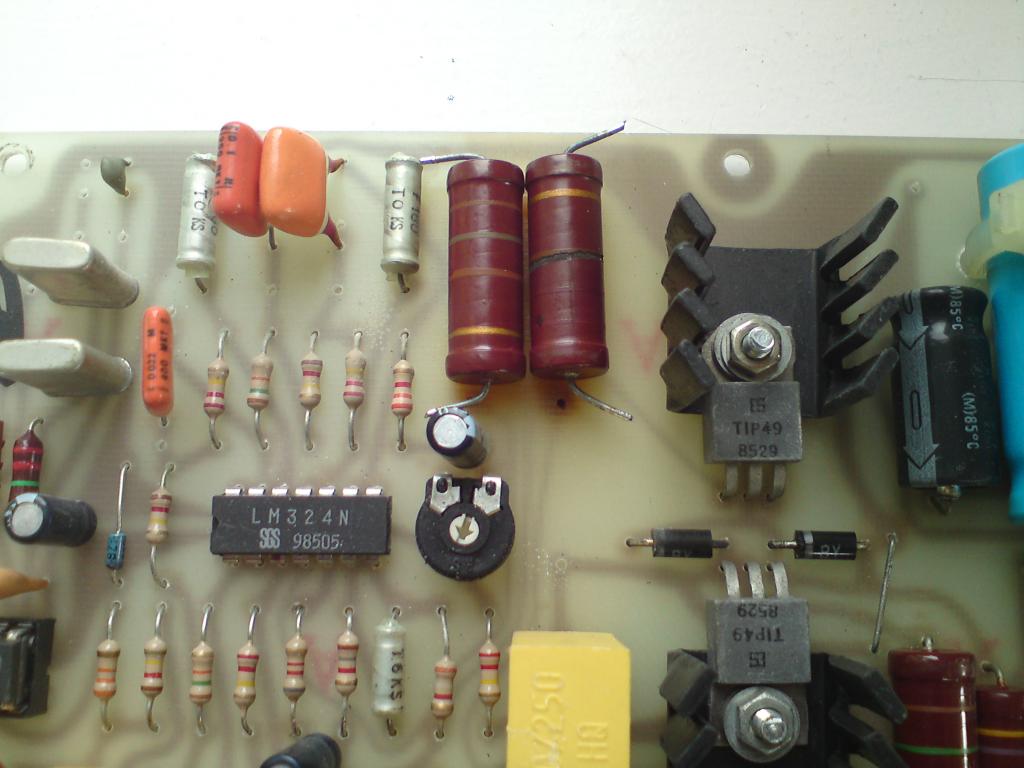
The problem seems to be resistor failure on the pcb, what a surprise!
Can anyone tell me what the resistance is of these resistors; one is still working and on a DDM seems to be 18K? Do you know the other and what wattage they are?
The photo shows them detached, but in their position.
many thanks
Cliff
I have Systemdek IV electronic that I have returned to after 10 years, it failed then and I stored it away.
The problem seems to be resistor failure on the pcb, what a surprise!
Can anyone tell me what the resistance is of these resistors; one is still working and on a DDM seems to be 18K? Do you know the other and what wattage they are?
The photo shows them detached, but in their position.
many thanks
Cliff
Attachments

I remember, long ago, that I replaced a power resistor which had burned like this on my brother's Linn Sondek power supply; this did not fix the supply since something else had failed first. Systemdek iv must be quite rare-I wonder if anyone else on the forum has one.
My guess is that they would be both the same value as the resistors are in series and both the same size and the heat damage to the PC board is about the same under both resistors. They look like 2W resistors to me. I would replace them with 2 18K 5W resistors.
I seem to remember someone using a 33K 10W resistor to replace both, but I could be wrong.
I seem to remember someone using a 33K 10W resistor to replace both, but I could be wrong.
Many thanks for the replies
I think I'll be lucky if this is the only problem.
I did scrape away the coating on the burnt resistor and try to measure either side of the damage with a DMM. I calculated it might be a 30k ohm resistor. Is this likely or should I just push on with two 18k? I am a novice to electronics. I assume they will fry again if wrong?
Cliff
...I calculated it might be a 30k ohm resistor. Is this likely or should I just push on with two 18k?
30k is highly unlikely! The product was made in the previous millennium and 30K is NOT a standard E12 value (every other resistor on the PCB appears to be from the E12 range).
2 x 18k (3 Watt or greater) wirewound resistors is what you require.
N.B. LINN use 2 x 15k wirewound resistors to perform the same function on the Valhalla and the AXIS. Bizarrely, they also mount the resistors too close to the PCB and also suffer from scorched fibreglass.
 😱
😱 In order to avoid further heat damage to the PCB, mount the resistors with a >10mm gap between their bodies and the PCB. Each 18k resistor dissipates approximately 1.25W.

Good Luck!
Thanks Hamish
How likely is this another problem other than resistors? Does the Linn have similar issues?
Cliff
How likely is this another problem other than resistors? Does the Linn have similar issues?
Cliff
It's impossible to say if there are any other pre-existing problems with the PCB. The easiest way to establish if there are any other issues with the PCB is to replace the resistors and test it.
 **** CAUTION - LETHAL voltages are present when connected to the mains ****
The electrolytic capacitors may be well past their 'sell by' date. The Zener diode may no longer 'Zener' (that's the blue thing to the left of the LM324 in your supplied picture).
There is nothing on the PCB that can cause the resistors to fail. They most probably fail because they're underrated for the application - they drop >300V DC @ >8.5mA. They each have a direct heat source adjacent to them (the other resistor) with zero airflow (enclosed space) to help dissipate the heat - less than ideal conditions for a 2 Watt carbon resistor.
Pop in to your local Maplin and buy 2 x 22k & 2 x 15k 'wirewounds' for less than a pint of Hoegaarden!
Good Luck!
**** CAUTION - LETHAL voltages are present when connected to the mains **** The electrolytic capacitors may be well past their 'sell by' date. The Zener diode may no longer 'Zener' (that's the blue thing to the left of the LM324 in your supplied picture).
There is nothing on the PCB that can cause the resistors to fail. They most probably fail because they're underrated for the application - they drop >300V DC @ >8.5mA. They each have a direct heat source adjacent to them (the other resistor) with zero airflow (enclosed space) to help dissipate the heat - less than ideal conditions for a 2 Watt carbon resistor.
Pop in to your local Maplin and buy 2 x 22k & 2 x 15k 'wirewounds' for less than a pint of Hoegaarden!
Good Luck!
Thanks again
You say buy two lots of resistors; is this to see which performs the best? The original I believe were 18K, could drop this to 15K as suggested? Or go to 22K?
Sorry for the numbskull approach, I can solder, but am not au fait with electronics.
Cliff
You say buy two lots of resistors; is this to see which performs the best? The original I believe were 18K, could drop this to 15K as suggested? Or go to 22K?
Sorry for the numbskull approach, I can solder, but am not au fait with electronics.
Cliff
Ideally, you'd replace 'like for like'. However, if your chosen supplier is Maplin, your choice of resistor values are limited.
See this.
It may be wiser to choose 2 x 15k + 1 x 22k + 1 x 10k - that'll afford you more flexibility with your combination of total resistance.
Start with 22k + 15k. If that combination is no good, try 22k +10k.
Good Luck!
See this.
It may be wiser to choose 2 x 15k + 1 x 22k + 1 x 10k - that'll afford you more flexibility with your combination of total resistance.
Start with 22k + 15k. If that combination is no good, try 22k +10k.
Good Luck!
Last edited:
Many thanks
One last question. If a resistor combination is not suitable can I assume the board just wouldn't work or might it work then fry?
Cliff
One last question. If a resistor combination is not suitable can I assume the board just wouldn't work or might it work then fry?
Cliff
Right. I have replaced damaged resistors with a wired 22k and 15k combination.
When the deck is started these resistors get extremely hot within a few minutes and the motor jerks, trying to start, then stops. Even with the deck off these resistors still seem to heat up.
Any ideas?
thanks
When the deck is started these resistors get extremely hot within a few minutes and the motor jerks, trying to start, then stops. Even with the deck off these resistors still seem to heat up.
Any ideas?
thanks
I'm going to have to get someone test this board. I live in Scotland at present. I need a repair centre that will take the board by itself, without the deck; is this possible?
Cliff
Cliff
Hi
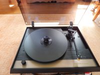
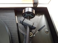
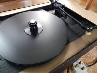
After sending the power supply away(£55.00 inc. delivery) the deck is now fixed - I have a working TT and a rare one apparently.
Anyone know the value of this deck on the UK market?
Some pics are enclosed.
thanks
Cliff
After sending the power supply away(£55.00 inc. delivery) the deck is now fixed - I have a working TT and a rare one apparently.
Anyone know the value of this deck on the UK market?
Some pics are enclosed.
thanks
Cliff
Attachments

Hi,
For sure it won't go on the open market for a price
commensurate with its performance capability.
I've tuned a IIX with the same arm, nice deck.
rgds, sreten.
For sure it won't go on the open market for a price
commensurate with its performance capability.
I've tuned a IIX with the same arm, nice deck.
rgds, sreten.
Looking at those first pictures, I see 180 ohm 2W. Not 18K. Looks like brown grey brown. Burnt one is obviously discoloured, but other looks as stated. Put a meter on the non burnt one. As they were in series only one would open. Other should be close to desired value. Also, when you replace them mout them up off board and a bit separated to permit airflow. Looks to me that failure was due to mounting them against the board, blocking cooling air.
Doc
Doc
Last edited:
- Status
- Not open for further replies.
- Home
- Source & Line
- Analogue Source
- Systemdek IV electronic - power supply failure