That is why Gigabyte motherboards have double the thickness!
(In before audiophile brands start marketing products with quad thickness... should i have kept my mouth shut?)
Nah, they'd just put black solder resist on it and call the PCB "special"...
The colour of choice seems to be green, 99% of the PCBs that pass my hands at work are some variation of green. Why? I don't know. We do see some other colours, like red, black or blue. My MSI motherboard is poo brown.... yuck...
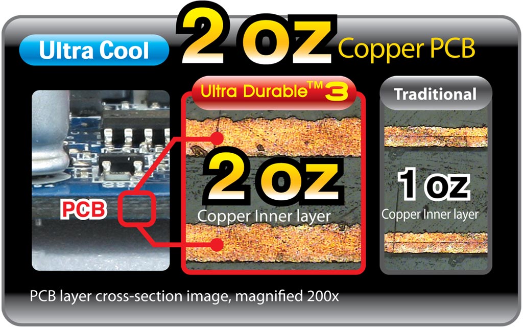
This Gigabyte add boasting 2oz (i.e. 70 um) copper is another example of marketing at its best. The use of 70 um copper isn't really special, but because of the higher cost only done when needed (large currents). If you look at the spec of a complex multilayer pcb, it's not unusual to see varying thicknesses depending on the function of a layer. No more copper is used than needed to save cost, even in expensive industrial applications.
Update: I still haven't replaced the caps yet but as I set the biases and the amp was working well on the bench, I thought I'd see how it sound in my 2ch rig. Something happened in the process of moving it upstairs and connecting. It now has a bad hum, goes in and out of protect and has either a 6V or -6V dc on the right channel whenever it comes out of protect.
Back on the bench, with nothing connected to the speaker output it is stable. As soon as I connect anything (DMM or scope probe) to the output, it starts cycling in and out of protect.
Background: The guy I bought it from said that it was supposed to be working fine when he got it. However, it had a hum and he immediately yanked it out and put it in the closet. I bought it cheap because of this and initially found it to be working fine (other than bulged caps). Now it has a hum. It seems to me that something has come loose.
I am going to order some caps and then yank it apart to investigate as it is a PITA to get to the bottom of the board. Now you all have me thinking about the bypass caps. It does have bypasses already.
sounds like an intermittent on feedback or the biggish shunt cap on the PA input is going leaky. intermittents are tough to find, I can usually use a heat gun and cool spray to find the leaky parts.Back on the bench, with nothing connected to the speaker output it is stable. As soon as I connect anything (DMM or scope probe) to the output, it starts cycling in and out of protect.
need more trouble shooting here, it shouldn't do that. might use a 10-20 ohm sand part, instead of speakers if you disable the protect. light bulb on the mains plug wouldn't be a bad idea either.
I read on another forum about a loose screw on the board causing similar issues in these amps.
I also saw where Mr. Curl eludes to upgrading a few parts resulting in nice SQ improvements. Unfortunately, he didn't spill the beans on what parts he was talking about.
Stan
I also saw where Mr. Curl eludes to upgrading a few parts resulting in nice SQ improvements. Unfortunately, he didn't spill the beans on what parts he was talking about.
Stan
why not bhc aerovox. i'm replacing them since they're 20 years old, just like the elna's rfs(just standard ones) and two are are cerafine, those may stay , but since they're sold , only in 10.000uF 63v instead of the 6800uF, i take those.
The problem often with changing caps for another brand is that besides nichicon and elna's, they get quite large often.
But they are cheaper then panasonic 10.000uF and 80v. And those ain't little i can tell you. Black ones , four pins 18euro; No special serie.
And nippon chemicon are nice and affordable and small built.
Roedersteyn F&T a. Love them, good price, only axial.
But i wouldn't take neither esr values , which difference is large with the stock once., just a good brand .
Greets Richard
Mr. Curl responded saying to change the electrolytics if I must but leave the film caps alone. I say he the man and it saves me time and money - cool.
Hello,
I am looking for some 10 mf radial ( lead connection is preferred) electrolytic caps 250 volts rating diameter 10mm or a few mm bigger. Height no problem.
Will be used for a choke input supply so there is not much of a ripple so they need to be a good '' reservopir '' cap.
Any suggestions are welcome.
greetings, Eduard
A choke input PSU has a very variable output voltage.
At the design current the output voltage is ~ 90% of the AC voltage fed to the rectifier.
At very low current demand the output voltage rises to ~140% of the (now unloaded) AC voltage fed to the rectifier.
The capacitors in the PSU must be selected to meet this worst case highest voltage.
ps:
what is a milli femto (mf)?
do you mean milli Farad (mF), or micro Farad (µF)
Hello Andrew,
There is a bleeder installed to take care of the minimum current required to make it work like a true choke input
The choke having lots of induction/inductance? doesnt require a lot of bleeding current just a few milliamprere.
The caps are 10 and 22 microfarad you can see that if you look at their seize.
I did make some choke input power supply before!
Now i am looking for some nice(r) caps. The choice is limited by the space available.
greetings, Eduard
Attachments
Farad has a capital F after the person's name.
m is milli. It seems you meant micro.
Beware the worst case highest voltage.
select for 55% to 60% of peak voltage and you could end up with exploding capacitors.
Bleeding could be done with a SHUNT regulator. When voltage is low the Shunt regulator turns off. When the voltage goes higher, the regulator turns on. It acts as an automatic bleeder. It is a "safety valve" to protect your capacitors and does not waste current all the time.
a good '' reservopir '' cap.
NICHICON CORPORATION | News Release | Addition to LD Series Extra Long Life Aluminum Electrolytic Capacitors
20.000hrs life expectancy for a 10uF/250V.
Clever name convention for their extra long life electrolytics.NICHICON CORPORATION | News Release | Addition to LD Series Extra Long Life Aluminum Electrolytic Capacitors
20.000hrs life expectancy for a 10uF/250V.
Use LD capacitors for Mains LED duty.
Even I should be able to remember that !
Hello Andrew,
Because of the 64 henry of the input choke i will only need to bleed around 3,5 milliampere. The high voltage regulators also '' bleed '' some current . So i did go for 4,5 ma bleeding current with the help of a resistor. Resistors if you dont let them fry seldomly fail. Chokes never fail unless you use them the wrong way. To much current and the inductance will collapse and they get warm.
To much ac voltage and they will '' spark '' but they are used well within their limits.
I will do some reading on the 250 volts caps. I still have a big stock of Black Gate VK 22microfarad 350 volts but they dont have leads and the diameter is to big to install them the proper way.
Have to make the original terminal a little longer by soldering a small piece of wire and then mount them a few mm above the circuit board. It can be done.
BUT have to find out first which 10 microfarad can be replaced by 22 without ending up with a circuit that will be malfunctioning.
Greetings, eduard
I am about to tear into an hca1000a that I got for my Mom here a while back.
I'm liking these for PS caps, great specs;
B41505A8688M EPCOS (TDK) | 495-6192-ND | DigiKey
The amp will also be receiving some nice polystyrene caps in place of the cascaded decoupling caps, as well as removing the bypass caps on the PS filter caps. A set of snubbers will be placed on the PS also, before the diodes.
The bias will be upped a bit to clean things up also, along with a fan.
I will be challenged to try and do some shielding of the transformer too while I'm in there.
It will be driving some 8" 2-way wall speakers that im redoing the crossovers with film caps, all using an arcam blink + power conditioner as a source.
I am curious for my own education and not disagreeing; what is the benefit of removing the bypass caps on the PS filter caps?
For shielding... ConneX Shielding
Thanks
Stan
For shielding... ConneX Shielding
Thanks
Stan
placing two capacitors in parallel increases the risk of ringing (oscillation of the voltage), when, or if, the cap is presented with a change in current demand.
Not having two capacitors in parallel avoids this potential instability.
Not having two capacitors in parallel avoids this potential instability.
One solution (if you really need the higher frequency/lower ESR of caps in parallel) is to add a third capacitor, maybe 0.1uf with a low-value (1 ohm) resistor in series with it. It works just like the snubber circuit at the transformer-rectifier connection.
This may happen when paralleling MLCCs, but with electrolytic caps with their higher ESR this should not be an issue.placing two capacitors in parallel increases the risk of ringing (oscillation of the voltage), when, or if, the cap is presented with a change in current demand.
Not having two capacitors in parallel avoids this potential instability.
- Status
- Not open for further replies.
- Home
- Amplifiers
- Power Supplies
- Power Supply Caps - Standard vs Audio