I just got 2 pairs of KLH Model Nines (Double Nines)...need some help.
Hello.
Well, just scored two pairs of KLH Model Nines, a pair of Double Nines 😀 They are all complete and in very good shape cosmetically. It belonged to a gentleman who bought them new way back and had it in his home for the last 40+ years. I have not tested them because I want to restore the electronics and crossover before I try anything.
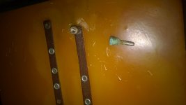
The first problem I have is that the small pin that connects to the banana plug which connects to the positive of the bias supply has broken off in all panels and one is missing. Looks like the banana plug connection to the female on the box got corroded and stuck to the box, so when they tried to move the box out it broke off at the panel side. So first question:
- how can I replace the small pin that comes out of the speaker so that I can screw the banana plug male connector to the speaker.
- where can I find a replacement banana plug with the screwed hole on one side to tie to the panel.
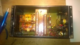
I have not brought the panels home yet...will pick them up next weekend. But I did bring all 4 power supplies/crossover boxes. I saw a nice write up on how to melt the wax to de-pot the box and how to replace the selenium diodes for silicon chains as well as replace the bias supply capacitors for ceramic. Of course I'll also replace the caps on the crossover.
I'd like to get my hands on the schematics for the bias supply and crossover, so I'd appreciate any help.
I did read a few posts by Mr David Janszen and saw the services he provides on the Janszen web site. It's great to know that it is available, but I'm limited on my budget now so I'm trying the DIY route first. I'm familiar with the electronics side so I'll start there.
I can wait to get these great speakers back to their former glory.
Thanks.
Elias
Last edited:
Quite amazing speakers, as I recall.
In the meantime, you might buy or build a high-voltage probe (200MOhms in series with 200KOhms which gives you 1000:1 reduction when measured across the 200kOhms). With a probe, assuming you are confident about working near high voltage, you can test.
I'd be lost these days without a mic and REW test software. And a Behringer DCX2496 digital processor to shape the sound and crossovers. Hard for me to picture how crude audio hobby work was before.
Ben
Keystone Electronics makes the threaded banana plug; see p/n 659 or 6074-2 for plugs with 6-32 threads. These are available from Mouser (or Keystone can provide samples).
Keystone Electronics makes the threaded banana plug; see p/n 659 or 6074-2 for plugs with 6-32 threads. These are available from Mouser (or Keystone can provide samples).
Thanks Mike. Found it on Digikey as well. Will order soon.
Does anyone know the caps values in the crossover of the KLH Nine?
Thanks
Elias
Speaker Builder article on Model Nine rebuilding
Hi.
I heard about an old article on Speaker Builder magazine about rebuilding the Model Nines. Anyone has a copy willing to share/sell?
Thanks
Elias
Hi.
I heard about an old article on Speaker Builder magazine about rebuilding the Model Nines. Anyone has a copy willing to share/sell?
Thanks
Elias
You can try contacting Mark Wilson at this address.
Mark was involved in the design of a lot of the KLH speakers.
If he still has any of the info yet.....
restorationATabsoundlabs.com
Mark was involved in the design of a lot of the KLH speakers.
If he still has any of the info yet.....
restorationATabsoundlabs.com
Restoration has started. Removed all banana plugs from the panels. Most had some kind of corrosion and rust. Ordered a whole new set for all panels.
Next, de-potted the first transformer box, replaced the diodes. Tested using clips and sounded great.
One down, three to go:

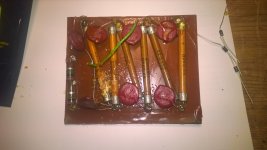
Here is the multiplier board with the original selenium rectifiers.

Now I have to figure out the right resistor to put in the AC input to lower the bias voltage to compensate for the silicon diodes. Don't have an electrostatic meter. Anyone willing to rent one?
Thanks
Elias
Next, de-potted the first transformer box, replaced the diodes. Tested using clips and sounded great.
One down, three to go:

Here is the multiplier board with the original selenium rectifiers.

Now I have to figure out the right resistor to put in the AC input to lower the bias voltage to compensate for the silicon diodes. Don't have an electrostatic meter. Anyone willing to rent one?
Thanks
Elias
NIce.Now I have to figure out the right resistor to put in the AC input to lower the bias voltage to compensate for the silicon diodes. Don't have an electrostatic meter. Anyone willing to rent one?
Thanks
Elias
see post 4.
I'd make the bias adjustable so you can lower it, if and when it seems too high.
Ben
NIce.
see post 4.
I'd make the bias adjustable so you can lower it, if and when it seems too high.
Ben
Agreed. I don't really want to drill and modify the original box beyond the 2 holes I had to drill to drain the wax. I used a variac to test it yesterday and I thought I'll have the boxes to connected to one at all times.
Thanks
Elias
Agreed. I don't really want to drill and modify the original box beyond the 2 holes ...
Thanks
Elias
I tend to regret not modifying more often.
but my wife watches Antique Road Show and thinks you shouldn't modify.
Ben
I tend to regret not modifying more often.
but my wife watches Antique Road Show and thinks you shouldn't modify.
Ben
That's funny! 🙂 My wife is the opposite...if I gave her the Nines she would rip the front cloth and replace with something else, stain the side wood darker and either cut the panels in half or lay them on the side. Of course she would get rid of those ugly looking black boxes 😱

Seriously though, I would probably need to have the pot for the adjustable bias outside the box anyway because of the wax. Might as well get a cool looking retro variac to go with the system.
Elias
Two of the panels are playing very low...why?
I replaced the diodes in two of the four boxes. I have 2 pairs of panels. One pair is numbered 01407 and the other 01606 the transformers are equally numbered. After replacing the diodes I tested both updated boxes with the 01407 pair and it sounds perfect. Unfortunately the 01606 pair is playing very low. Things I tried:
- obviously the updated box is fine because the 01407 pair plays fine. So it's not the bias circuit.
- I removed the back panel of one of the 01606 panels and checked all connections and wires and all seems perfectly fine.
- When I fire the amp without the bias the sound is very faint, as expected. When I turn the bias on the sounds increases but just a little bit. All woofer panels and the tweeter play at the same low level. So the only thing that could be affecting all panel at the same time is the bias. But the bias board is fine because the other panels are playing fine. 😕
I find it hard to believe that the all woofers and the tweeter failed equally 😕
Also, that the woofer and tweeter bias wires (which are separate) also failed equally.
So my suspicion is that there may be a bad ground connection.
Any suggestions / ideas??
Thanks
Elias
1. Have you measured the bias with the little circuit I described earlier?
2. Was my description too obscure? If it was too obscure then maybe you should be very cautious about measuring high voltages, even if you buy a high voltage probe appendage for your digital voltmeter.
Does anybody know if you can test HV by moving a neon bulb near the voltage or some easy way that doesn't involve raising your hair on end, for those of us without cooperative hair.
Ben
Ben
Last edited:
1. Have you measured the bias with the little circuit I described earlier?
2. Was my description too obscure? If it was too obscure then maybe you should be very cautious about measuring high voltages.
Ben
Ben
1 - Not yet. I have ordered a HV probe and should be here soon.
2 - No, your description was not obscure. I did build a couple of voltage dividers using 10 x 22 Mohm resistors in series for another bias supply I built. Don't worry, I'm very, very cautious around HV.
Regardless, the same bias supply drives one panel perfectly well. I'm listening to it right now and it sounds wonderful.
Could it be that the bad panel is loading the supply too much?
Thanks
Elias
Could it be that the bad panel is loading the supply too much?
Thanks
Elias
I understand that the membrane coatings increase in resistance over the years. So it can take a few hours to charge.
You can check things by putting a large resistor, such as 50 megOhm in series with the panels. It would have no influence on my Dayton-Wright panels but it there was much of a voltage drop across that resistor, then the panels might be shorting away the bias.
Ben
I thought about the increase in resistance due to membrane aging. Maybe I'll leave it on for a few hours to see if gets any better.
If not, I'll definitely try a resistor in series as you suggested.
Thanks
Elias
- Status
- Not open for further replies.
- Home
- Loudspeakers
- Planars & Exotics
- So, I just got 2 pairs of KLH Model Nines (Double Nines)...now let's get to work...

