The trafo is to connect between the headphone amp and the headphones. You have two 115V primary windings (going to the amp) - connect these in parallel. The secondaries are 18V (they go to the 'phones) - you can connect in series to give *3.2 step down or in parallel to get *6.4 reduction. You'll need two trafos for the two (stereo) channels.
Yes I've noticed that plenty of people say that low output impedance is desirable for a headphone amp, the trafos I've linked to will have considerable winding resistance though so probably not the lowest. If you really want low output impedance you'll need to get into winding your own trafos as stock mains trafos are designed for much higher voltages than come out of headphone amps - rewinding them with fewer turns (but thicker wire) gets lower Zout.
<edit> I forgot to mention - you should include a coupling capacitor between the amp and the primary to stop DC getting to your trafo. An electrolytic of 470uF/25V should do the job nicely.
Last edited:
Yes - I use a resistor this big on TL084s as they have such a low drive capability and being JFET types current noise isn't an issue. CFB opamps are another matter entirely, I wasn't talking about them. For those you need to use low impedance feedback networks or you don't get the bandwidth. For such I'll load the output with a current source to prevent it going into classB.
With bipolar input opamps you need to be concerned about current noise from higher valued resistors - so stick with JFETs unless you're going to bias up the OPS.
Thank you for the explanation. I almost always use and prefer the sound of bipolar input op-amps to JFETs, but I know their higher input bias currents and resulting offset can be a problem.🙂
Are you a fan of the TL0XX series? I was under the impression most folks have moved on to something newer/(supposedly)better.
I can't say much about the older stuff as I still like the ole' LM833.😱
This has made me recall that in the past I've seen high end hifi people recommend "in line attenuators" between the source and the amplifier in order to avoid clipping. Is there any reason that these trafos couldn't be used in the same way?
I used to prefer bipolar opamps (being a fan of NE5532 for quite a while). Now though I use TL084s for active crossover duty and make sure the power supply's as clean as it possibly can be (by running fully balanced with high circuit impedances). To my ears, that's good enough and TL084 can't be beaten on price. I reckon my poweramps are the limitation on SQ, not my opamps - simply because the TL084s are comfortably in classA and my poweramps would get way too toasty if I ran them pure classA.
This has made me recall that in the past I've seen high end hifi people recommend "in line attenuators" between the source and the amplifier in order to avoid clipping. Is there any reason that these trafos couldn't be used in the same way?
I don't generally recommend those resistive attenuators - they can work certainly but don't deliver the best sound (this has nothing to do with the quality of the resistors fitted inside though). If you do more research you'll find the discerning listeners tend to prefer 'TVCs' for volume control and what you'll be using is simply a fixed version of that. Audiophile grade attenuation 🙂
The TPA is a current feedback device too and with the standard inverting 1k ohm everywhere design (as is nominal from the datasheet) you end up with a gain of 2. So not only do you appear to possibly have some gain around the input buffer stage, but you've also got some gain around the TPA as well.
I have never understood why anyone would put some gain in the buffer before the TPA as the 2x that the chip provides in its standard configuation is more than enough to make your ears explode even with insensitive high impedance phones.
As the standard configuration for the TPA is inverting it makes sense to use an inverting input buffer as well. This will invert the signal twice and hence cause no signal inversion from the input to the output of the device.
Next to the OPA you've got two 30k resistors, one 10k resistor, one 1k resistor and one 10R resistor. The 1k resistor will be on the output of the OPA and will feed directly into the TPA chip. My guess would be that the 10R resistor is connected between the non inverting input of the opamp and ground. This leaves the two 30k resistors and one 10k resistor for setting the feedback.
What the configuration of these will be is anyone's best guess, but I doubt they've got it configured to give negative gain of any sort. They also do not specify what the devices input impedance is either so we cannot use that to help define how the resistors have been configured.
It would seem silly to go about using something as over the top as a transformer when all one needs to do is map out the circuit diagram of how the resistors are connected with a multimeter and then most likely change one resistor.
Even at a very basic level changing the two 30k resistors to 10k would probably be a safe bet. Or even easier simply lowering their value by soldering a 15k resistor in parallel with each 30k one.
It would seem silly to go about using something as over the top as a transformer when all one needs to do is map out the circuit diagram of how the resistors are connected with a multimeter and then most likely change one resistor.
Perhaps you missed the post where the OP mentioned a pre-existing medical condition which precludes him doing fine manual work like desoldering SMT parts?
Trafos will probably make this beast sound more dynamic and they're what, 3 quid a pop. What's not to like - resale value is preserved if that's of any consequence.
You do not need to de-solder the SMT parts, simply solder a couple of 15k resistors on top of the current 30k ones. This isn't all that hard and steady hands aren't really required, you can hold the 15k resistor in a pair of large tweeters or glue them to the tip of a match stick for placing. When I solder SMT I always have the hand that is holding the tweezers resting on the table, as if I were holding a pen. This completely stops my hand from shaking. I do the same with the soldering iron in the other hand.
I had read that fine manual dexterity would be a problem, but I don't consider largish SMT resistors like these (they look like 0805s to me), especially on low density and easily accessible boards, particularly demanding. It depends on what kind of physical handicap our poster here has. If it's just a case of taking ones time and repeating the same motion over and over again until you actually get it right then I'd say it's worth it. Sometimes I spend 30 minutes until I manage to place a tiny SMT IC correctly, it's frustrating, but if my 30 minutes for a tiny SMT IC with loads of pins is thedman's 30 minutes per resistor then it'd be worth it imo.
The more important question I think would be if thedman has the required tools to solder etc and if he does maybe another person could do the soldering for him. As a shot in the dark though, thedman where are you in the UK? If you're local I could do it for you.
I'll look into it. I had no idea transformers were so well regarded. Very old school!
Because they aren't generally. They will introduce distortion, non-linearities and limit bandwidth so it's better not to use them unless really needed. Even expensive audio transformers from serious manufacturers have serious limitations.
Don't take me wrong, I've used transformers in the past and will continue to use some. But in this particular case, changing the input opamp gain is indeed the best option.
The trafo is to connect between the headphone amp and the headphones. You have two 115V primary windings (going to the amp) - connect these in parallel. The secondaries are 18V (they go to the 'phones) - you can connect in series to give *3.2 step down or in parallel to get *6.4 reduction. You'll need two trafos for the two (stereo) channels.
Yes I've noticed that plenty of people say that low output impedance is desirable for a headphone amp, the trafos I've linked to will have considerable winding resistance though so probably not the lowest. If you really want low output impedance you'll need to get into winding your own trafos as stock mains trafos are designed for much higher voltages than come out of headphone amps - rewinding them with fewer turns (but thicker wire) gets lower Zout.
<edit> I forgot to mention - you should include a coupling capacitor between the amp and the primary to stop DC getting to your trafo. An electrolytic of 470uF/25V should do the job nicely.
Perhaps buying a few and parallel the secondaries? Not sure in what range the DCR is like for miniature power transformers, but should help with the primary side too?
There's a trade-off as all transformers have core losses, not just copper losses. So I think if the copper loss is significant (its probably able to be calculated from some of the technical data provided) then all in all it'll be better to choose a higher VA trafo rather than parallel smaller ones. Paralleling also increases the shunt capacitance.
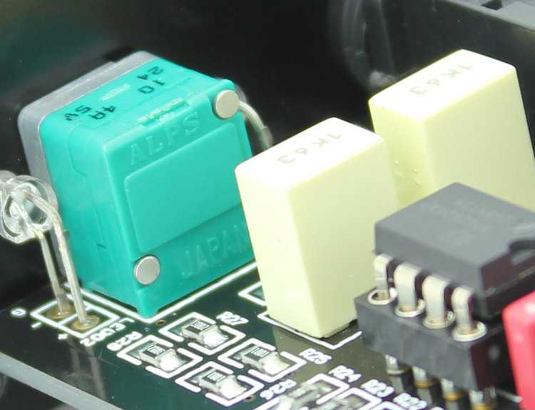
Here is a close up of the pot. Does the marking that says 7A mean this pot gives 7% of its power at the midpoint? If so would that be unusual? I thought 15A was the norm?
An externally hosted image should be here but it was not working when we last tested it.
Here is a close up of the pot. Does the marking that says 7A mean this pot gives 7% of its power at the midpoint? If so would that be unusual? I thought 15A was the norm?
I don't seem to be able to edit my post so I'm replying to it instead. I think the letter A means it's a standard 15 taper - but I don't know what the number 7 before the A stands for?
Sorry to necro a thread but did anyone determine exactly what resistors needed changing? I'm running the sap II atm and love it but it is far too loud. 😱
Just bumping this thread up for you as you won't trigger the thread notifier while still under moderation.
Also see,
http://www.diyaudio.com/forums/headphone-systems/287491-smsl-sap-ii-too-loud.html#post4629102
Also see,
http://www.diyaudio.com/forums/headphone-systems/287491-smsl-sap-ii-too-loud.html#post4629102
- Status
- Not open for further replies.
- Home
- Amplifiers
- Headphone Systems
- Using sApii Pro TPA6120a2 at lower voltage?