The picture the OP showed as a possible example to follow had separate RCA for each channel, so separate ground connections for each incoming cable are possible. A stereo patch cord does not have to have a common ground; it could be two electrically separate cables which are physically joined by a piece of insulation. It's really hard for me to believe you didn't already know this.bentsnake said:Actually no, there isn't always a pair, for instance now. The ideal scenario you describe is unfortunately impossible because the the left and right channels of a stereo patch cord share a common ground/return: the shield. It's really hard for me to believe you didn't already know this.
A circuit cannot exist unless there is both a flow and a return for the signal to pass from the SOURCE and return to the SOURCE.
...the the left and right channels of a stereo patch cord share a common ground/return: the shield..
You know this as well as DF96 does.
.
A stereo patch cord does not have to have a common ground; it could be two electrically separate cables which are physically joined by a piece of insulation.
Of course one could get into multi-conductor cables, but I don't see that as being appropriate to the project described.
Everybody who actually reads these things, raise your hand. Hmmm, no hands.
.
A nexus, as it were.
.
In post #1 a question was asked.
In post #9 the question was answered. A circuit was posted.
1. Does anybody think the posted circuit won't work?
2, If you think it won't work, perhaps you'd be so good as to post a circuit that will.
.
.
In post #1 a question was asked.
In post #9 the question was answered. A circuit was posted.
1. Does anybody think the posted circuit won't work?
2, If you think it won't work, perhaps you'd be so good as to post a circuit that will.
.
Last edited:
What is so rare and complicated about "multi-conductor cables" that, in your view, we don't have to consider them? The OP showed an example using RCA, which can use common or separate ground (mostly separate, in my experience). Your suggestion used TRS, which necessarily uses a common ground.
Why does everything have to get so complicated? The OP needs a switch in a box and some wiring. If he wants low interference/hum then he needs to get the wiring right, but this is not difficult. He just needs to ignore the example he showed, and instead use twisted pair or screened cable. If hum etc. is not an issue then anything will do.
Why does everything have to get so complicated? The OP needs a switch in a box and some wiring. If he wants low interference/hum then he needs to get the wiring right, but this is not difficult. He just needs to ignore the example he showed, and instead use twisted pair or screened cable. If hum etc. is not an issue then anything will do.
What is so rare and complicated about "multi-conductor cables" that, in your view, we don't have to consider them? The OP showed an example using RCA, which can use common or separate ground (mostly separate, in my experience). Your suggestion used TRS, which necessarily uses a common ground.
Why does everything have to get so complicated? The OP needs a switch in a box and some wiring. If he wants low interference/hum then he needs to get the wiring right, but this is not difficult. He just needs to ignore the example he showed, and instead use twisted pair or screened cable. If hum etc. is not an issue then anything will do.
Perhaps you'd be so good as to post a circuit such as you describe. With the wiring right and all.
.
Yes, we (DF96 and Andrew T) both know how circuits allow flow and return currents.
You seem to think that it is different:
You seem to think that it is different:
Actually no, there isn't always a pair, for instance now.
Yes, we (DF96 and Andrew T) both know how circuits allow flow and return currents. You seem to think that it is different:
1. Does anybody think the posted circuit won't work?
2, If you think it won't work, perhaps you'd be so good as to post a circuit that will.
Step forward into the light of day and make yourself known like an honest man. Circuit. Work. Yes. No. Speak.
.
I don't think the OP needs a circuit to show him how to wire a 2-pole switch.
Dunno why you're telling me this. If you're not sure, perhaps you should ask the OP?
Haha, just kidding, of course. The OP has long since despaired of getting any help around here and left. He's probably taken up needle point.
In a sidebar, would you care to make yourself known? The circuit in post #9? Work? No? Yes? Got something better?
.
Last edited:
I would be very interested as I am building something similar, however, I'm using 4PDT switches. A mechanical drawing of the ground connections using standard female RCA jacks would be very helpful. I had planned to connect all the ground tabs for the rca jacks together and then run a wire from just one of the rca jacks to the switch and then to the chassis. The switch has no ground tab so I was going to solder a ground lug directly to the body of the switch. I'm using these switches: 4PDT Heavy Duty Toggle Switch
Of course, the rca jacks would be isolated from the chassis.🙂
Of course, the rca jacks would be isolated from the chassis.🙂
In a sidebar, would you care to make yourself known? The circuit in post #9? Work? No? Yes? Got something better?
.
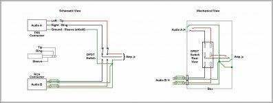
In the mechanical drawing in post 9 the sockets should be isolated from the box.. so that the box is just an earthed enclosure and not part of the signal path..😛
The toggle of the switch should be in contact with the box to stop pick up..and I prefer phono connectors to the jack sockets.
So yes it will work..but as always there is are different ways ...
So whack a toggle in and the jobs done..sniff..😀
However I don't like the shared Ground cables..its not HIFI..its more like guitar..The left and right channels should have their own ground circuit.
You can combine and split and share a ground however the box should only be grounded at one point.
Regards
M. Gregg
Last edited:
Are you asking if it will work because you are not sure, or is this just some sort of debating point?bentsnake said:In a sidebar, would you care to make yourself known? The circuit in post #9? Work? No? Yes? Got something better?
It will work if the sources and output use TRS connectors, which imply a common ground for the two stereo channels. It will not work if he requires separate cables into RCA connectors, as used in most domestic stereo systems. It might not work if he requires low hum, as there will be a loop formed by the signal and return wires. OK?
Are you asking if it will work because you are not sure, or is this just some sort of debating point?
It might not work if he requires low hum, as there will be a loop formed by the signal and return wires. OK?
ER a ground is a ground isn't it..😀
well NO because they could be at different potentials..
But its a ground... 😀 no it isn't ..yes it is..but...LOL
OK its voting time when is a ground a ground...answers on a postcard to...
Bentsnake look here..and read the grounding section..page 7
http://glass-ware.com/User_Guides/ACF 9-Pin.pdf
Next question when can current flow in a ground ?
OK well when is ground an earth..OH nooooooo...
An earth is earth isn't it..well there is noise on an earth....but its ground well it could be earth..but filters have connections to Earth..so...😀
Well its Ground so it doesn't count..stop confusing the issue..Im not its ground..well what about Earth...
 ..
..Sorry couldn't resist..
Regards
M. Gregg
Last edited:
I would be very interested as I am building something similar, however, I'm using 4PDT switches. A mechanical drawing of the ground connections using standard female RCA jacks would be very helpful. I had planned to connect all the ground tabs for the rca jacks together and then run a wire from just one of the rca jacks to the switch and then to the chassis. The switch has no ground tab so I was going to solder a ground lug directly to the body of the switch. I'm using these switches: 4PDT Heavy Duty Toggle Switch
Of course, the rca jacks would be isolated from the chassis.🙂
It's all sameO, really. The below might help. Look at Audio B. The notes in post #9 apply.
<< I had planned to connect all the ground tabs for the rca jacks together and then run a wire from just one of the rca jacks to the switch and then to the chassis. >>
Without knowing exactly what you're doing, this could be iffy. It was commonly done with tube (valve) circuits, but the much lower currents and voltages of ICs are a different story.
If I understand, you're not going to terminate the switch box end of the RCA plug shields at all? They'll just float? In that case the shields can, under some conditions, become radio antennas, which obviously is not wanted.
Otherwise, you have the shield of each RCA cable being ground, and yet another ground conductor being run, all terminating in your switch box? Then I don't see the point of the additional ground conductor.
Or if you're not going to connect some of the shields at all, then the audio signal is not shielded, which defeats the whole purpose.
Personally, I think I'd plug into RCA jacks on the switch box, then bring the grounds together only to exit the box.
<< The switch has no ground tab so I was going to solder a ground lug directly to the body of the switch. >>
The switch body is made of steel, which doesn't accept solder well (Altoids boxes, and some switch covers, are made of steel coated with tin, the tin does accept solder). The usual way to ground a switch is by putting a wire between the switch and the chassis, and tightening the mounting nut. The uptown way is to get a ring-type solder lug that will fit over the switch threads.
Although actually the switch is shielded by the metal enclosure (if the enclosure is grounded), so it's usually not really necessary in the first place.
I guess I do have to say that I've seen some problems solved by grounding a switch or similarly unlikely component, but it's rare.
.
Attachments
Last edited:
It might not work if he requires low hum, as there will be a loop formed by the signal and return wires. OK?
Low hum? There's a concept for ya.
On a grimmer note, no, things are far from OK. Expert A says there must be a loop. Expert B says there's always a loop. Expert C says a loop will cause hum. Hey waitress, we'll all have Fruit Loops. Get your stories together.
Of course the best way to solve that problem is by posting the circuit you propose.
.
Last edited:
It's all sameO, really. The below might help. Look at Audio B. The notes in post #9 apply.
Thank you, your drawings were helpful. I probably should have been more specific with what I'm building. I'm building a switch box that will allow me to use 2 different amps with the same sets of speakers. This involves 2 4PDT switches...up is one amp and down is another amp. One of the switches is for the left and the other for the right. I'm using dual banana plugs.
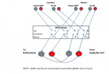
The box will also allow me to use the same tube buffer with the 2 different amps via a 3rd 4PDT switch. The amp outs will connect to rca in jacks on the box. The rca jacks will then go to the switch...up is one amp and down the other amp. From the switch, the signal will connect to the output rca jacks. Those output rca jacks will then connect to the amp in jacks. The common terminals on the switch connect to input rca jacks and then to the output rca jacks. I'll try to post a layout.
Thank you, your drawings were helpful. I probably should have been more specific with what I'm building. I'm building a switch box that will allow me to use 2 different amps with the same sets of speakers. This involves 2 4PDT switches...up is one amp and down is another amp. One of the switches is for the left and the other for the right. I'm using dual banana plugs.
The box will also allow me to use the same tube buffer with the 2 different amps via a 3rd 4PDT switch. The amp outs will connect to rca in jacks on the box. The rca jacks will then go to the switch...up is one amp and down the other amp. From the switch, the signal will connect to the output rca jacks. Those output rca jacks will then connect to the amp in jacks. The common terminals on the switch connect to input rca jacks and then to the output rca jacks. I'll try to post a layout.
Do you intend to switch with the amps powered up?
Its not a good idea to have an amp with speakers disconnected and accidently switch it on..
So if I was doing this I would have a dummy load on the amp with speakers disconnected..Watch for thump if you switch the inputs over..
Regards
M. Gregg
Do you intend to switch with the amps powered up?
Its not a good idea to have an amp with speakers disconnected and accidently switch it on..
So if I was doing this I would have a dummy load on the amp with speakers disconnected..Watch for thump if you switch the inputs over..
Regards
M. Gregg
Thanks for the heads up
 . In my research before building, I did run across some folks that encountered this so I had planned to only switch when the amps are off. I'm pretty good <cough...anal...cough> about turning my gear on and off in order to minimize thumps from the amp to the speakers.
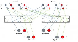
- Status
- Not open for further replies.
- Home
- Source & Line
- Analog Line Level
- Building a decent input switcher