If the input resistor is 82k to 100k, then a 1uF cap gives an LF roll off about a decade below the 20Hz start of the Audio band.
A 1uF MKP, or MKT, will cost much less than $11.30
If one retains the 22k for the input resistor to suit BJT LTP, then you are stuck with 4u7F for the decade wider passband.
However if the jFET LTP were adopted, then there is no reason to use the 22k input resistance. Use 82k, or 91k, or 100k.
A 1uF MKP, or MKT, will cost much less than $11.30
If one retains the 22k for the input resistor to suit BJT LTP, then you are stuck with 4u7F for the decade wider passband.
However if the jFET LTP were adopted, then there is no reason to use the 22k input resistance. Use 82k, or 91k, or 100k.
Somehow I never did order (or couldn't find) the relay for the new Symasym BB Rev2 boards. Except for the silkscreen I can't find the full part number or spec. It was left off the BOM and it's not mentioned anywhere in the builder's guide. Just want to confirm this is the correct one before I order. Is it in fact a 24v relay?
Rick
Rick
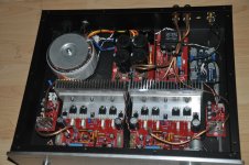
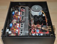
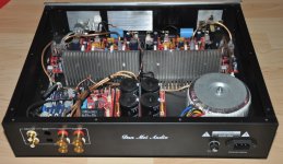
I have bought cristi289's Symasym TO264 power amplifier (pot and attenuator removed). I believe Rudi built it some time ago. It sounds great.
Are there any upgrades i could make to the amp that members have tried that would make an improvement in sound quality?
Are there any upgrades i could make to the amp that members have tried that would make an improvement in sound quality?
Attachments
Maybe installing some 2sk170 on input ?I have bought cristi289's Symasym TO264 power amplifier (pot and attenuator removed). I believe Rudi built it some time ago. It sounds great.
Are there any upgrades i could make to the amp that members have tried that would make an improvement in sound quality?
Maybe installing some 2sk170 on input ?
Thanks for suggestion. Will do a bit of research
Andrew already give all info. Change de two input transistors to preferably matched 2sk170 and also the 22k input resistor to 100k and thats all. Everybody agrees thats sonds better. I can confirm also from my experience.
Sent from my iPad using Tapatalk
Sent from my iPad using Tapatalk
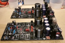
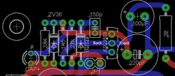
A bit more progress on the project. Completed most of the second board this weekend. Was having second thoughts on the Q80 (KSC3503) and Q81 ( KSA1381) orientation, and had to follow the schematic to make sure. Glad I did, because I had them backwards on the first board. 😱 On those particular plastic TO-126 package it's difficult to know what's the front and back, as there's no distinct markings and the pins are only slightly offset. And I had some trouble with the silkscreen on the PCBs too. But I figured it out. 😱
I'm waiting on the chassis and heat-sinks now, so I can prep them for installation and testing.
I'm waiting on the chassis and heat-sinks now, so I can prep them for installation and testing.
Attachments
I habitually test the hFE of every BJT I intend using in an amp assembly.
Using the hFE test facility of a cheap DMM solves your identification issue. It is a non problem.
record your hFE and use it to check base current in your testing of the circuit.
Using the hFE test facility of a cheap DMM solves your identification issue. It is a non problem.
record your hFE and use it to check base current in your testing of the circuit.
Printing the "e" of every transistor on the silk screen would help all Builders.
Even the T092 devices would benefit from the lack of ambiguity.
Even the T092 devices would benefit from the lack of ambiguity.
Do I have to use special 100nF capacitors on the Black Beauty Rev.1?
The Wimas of the Rev.2 Bom dont fit.
The Wimas of the Rev.2 Bom dont fit.
are the 100nF for supply rail decoupling duty?
If so then use X7R ceramic in the highest capacitance value that fits the smallest package size.
Try 220nF 100V 0.1" or 0.2" pin pitch if they are through hole type.
If so then use X7R ceramic in the highest capacitance value that fits the smallest package size.
Try 220nF 100V 0.1" or 0.2" pin pitch if they are through hole type.
I dont think thats the duty oft C3, C12 and C14. Also which cap should I buy for C15 (the output-grounding)
Refer to this BoM please:
https://secure.reichelt.de/index.html?&ACTION=20&AWKID=1056168&PROVID=2084
Best regards - Rudi
https://secure.reichelt.de/index.html?&ACTION=20&AWKID=1056168&PROVID=2084
Best regards - Rudi
Thanks for your help. Is there a specific schematic for my version of the symasym board (TO264). Struggling to find it!
I agree. In this situation I was clearly blaming the part for not being well marked and the data sheet did not help. It's not always the silkscreen either. I was trying to place some radial electrolytics for another project and neither side was marked with a negative or positive sign! I don't think you should have to resort to the length of the leads to determine proper orientation. They could have been cut for any number of reasons or might be axial leads. And there should be global standards too. 🙂Printing the "e" of every transistor on the silk screen would help all Builders.
Even the T092 devices would benefit from the lack of ambiguity.
Last edited:
I used a little transistor testing rig I have to ultimately figure out what the pins were. Then using the schematic, the proper orientation.I habitually test the hFE of every BJT I intend using in an amp assembly.
Using the hFE test facility of a cheap DMM solves your identification issue. It is a non problem.
record your hFE and use it to check base current in your testing of the circuit.
- Home
- Group Buys
- TO-3 SYMASYM