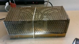
I have come to possess a chassis for a tube amplifier I believe was built in the 1960s. The schematic and parts labelling are readily available online.
I would like to rehab this device, but there are several problems.
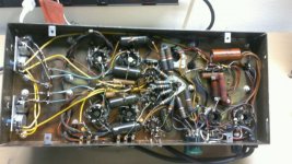
The electronics are in good shape except for a burnt capacitor and resistor and a couple of inches of burnt wire, easily replaced, next to the capacitor
In theory I can use the existing arrangement, as built. I should replace all the capacitors, correct? What about the resistors? Should I check each resistors value and only replace those with out of range readings?
Of course, there is the purchase of 8 vacuum tubes.
The chassis is not in good shape. There is missing paint and corrosion. It would be difficult to improve this with a hand dremel tool, and it will never really look good. This call's for a new chassis. Now, how to get all the wiring out of the 1960s box into a new one- the issue would be the vacuum tube holders, which are riveted in place.
Si I am asking for advice. When I first spied the chassis in a fore closed home I thought first of just using the transformers, but there are more options, as I have written.
I would like to rehab this device, but there are several problems.
The electronics are in good shape except for a burnt capacitor and resistor and a couple of inches of burnt wire, easily replaced, next to the capacitor
In theory I can use the existing arrangement, as built. I should replace all the capacitors, correct? What about the resistors? Should I check each resistors value and only replace those with out of range readings?
Of course, there is the purchase of 8 vacuum tubes.
The chassis is not in good shape. There is missing paint and corrosion. It would be difficult to improve this with a hand dremel tool, and it will never really look good. This call's for a new chassis. Now, how to get all the wiring out of the 1960s box into a new one- the issue would be the vacuum tube holders, which are riveted in place.
Si I am asking for advice. When I first spied the chassis in a fore closed home I thought first of just using the transformers, but there are more options, as I have written.
Attachments

You can defeat the socket rivets with a small burr in your dremel. IMO, it is probably easier to buy new sockets for the new chassis.
The old carbon composition resistors need to be checked for noise and drift. Unless they are showing signs of physical damage, leave wirewound resistors be.
If you don't use the amp to power a preamp, replace the non-linear 12AU7 with a 12BH7. If you do power a preamp, use the Loctal based 7AF7 as the replacement for the 12AU7. The associated passive parts values do not change.
The first thing to do is to verify the transformers are good. The transformers are the most expensive thing to replace, so if the amplifier has been stripped of tubes and put aside, it is possibility you must consider that a transformer is crook, and that is the reason it was put away in some shed where it go the corrosion.
There's abit of rust on teh transfomers. Do not attempt to remove it. If they test good, just re-spray them with matt black paint of the sort designed to go on itemns with mild surface rust, and they'll look good.
To test the power transformer, disconnect all secondaries and apply AC mains to the primary via a 60W lamp. If the lamp glows, the transformer is crook. If not, measure all secondary and primary voltages. If one or more is significantly lower than it should be, the transformer is crook. Internal shorts may or may not cause excesive heating. (I have an item on the bench now - the previous owner thought the tubes were weak. However a shorted turn in one of teh heater windings is holding voltages down about 15%. The transformer is not abnormally warm.)
Of couse, if your transformer is getting hot (it amy take an hour or more to build up heat), it may be crook.
As you have two output transformers, test by measuring the inductance of all windings, each in turn with the other windings open. Both transformers should test approximately the same.
If you are not sure how to test inductance, tell us what test gear if any you have.
If all three transformers are good, I guess you have three choices:-
a) recycle the transfomers in a complete new tube project. This is the choice I would take.
b) use this amp as a basis of making a copy with a new chassis, new tube sockets, new everything except the transformers. By new I mean really new or NOS or used known good.
c) sell the transfomers on eBay and throw the rest out.
Pilot amps were high quality esp. The output transformers. You might try flipping it on eBay or reuse the OPT
I've seen someone completely disassemble one of these,sand, paint and reassemble it to awesome condition,They painted the chassis and cage gold, similar to the original cage color
Indeed. I've known people to completely strip, sand, paint, etc too.
But it is simpler to just use the original as amodel to copy from. Make drawing of the chassis and make a new one. You can even have it cadmium plated and passivated just the same as the original, instead of paint that just ressembles the original. Use all new parts except for the transformers.
After all, what do we have in the original:-
1. The chassis - it's just a piece of stamped and bent sheet metal
2. Resistors - they are all suspect. Many will need to be replaced. New one cost cents, so there is no need to recycle.
3. Capacitors, electrolytic - all will need replacing, even if they test not too bad.
4. Capacitors, non lectro - all coupling caps are probably leaky and will have to be scrapped.
5. Pots - will be dried out, worn, and noisy if not actually intermittant. Some CRC will make them quieter, but only for a while. Best replaced with new.
6. Tube sockets - as the tubes are long gone, sockets will be in bad shape from dust. Need replacing.
What's left? Maybe some tagstrips. A few bits of daggy old wire. Big deal.
Last edited:
Indeed. I've known people to completely strip, sand, paint, etc too.
But it is simpler to just use the original as amodel to copy from. Make drawing of the chassis and make a new one. You can even have it cadmium plated and passivated just the same as the original, instead of paint that just ressembles the original. Use all new parts except for the transformers.
After all, what do we have in the original:-
1. The chassis - it's just a piece of stamped and bent sheet metal
2. Resistors - they are all suspect. Many will need to be replaced. New one cost cents, so there is no need to recycle.
3. Capacitors, electrolytic - all will need replacing, even if they test not too bad.
4. Capacitors, non lectro - all coupling caps are probably leaky and will have to be scrapped.
5. Pots - will be dried out, worn, and noisy if not actually intermittant. Some CRC will make them quieter, but only for a while. Best replaced with new.
6. Tube sockets - as the tubes are long gone, sockets will be in bad shape from dust. Need replacing.
What's left? Maybe some tagstrips. A few bits of daggy old wire. Big deal.
Good luck finding someone to cadmium coat anything. Its not done anymore do to toxicity of cadmium.
Good luck finding someone to cadmium coat anything. Its not done anymore do to toxicity of cadmium.
Cadmium plating should not be done on parts coming into contact with food. It also should not be abraded, ground, or welded, as inhalation of cadmium dust causes a temporary feeling of weakness and is thought to increase the probability of prostate and breast cancer slightly. Using household insect sprays is a vastly more health hazard by comparison.
It is banned in Europe - but their politicians will ban just about anything. They banned lead in solder but the environment impact is minute and the impact on blood lead levels in persons doing soldering is maybe 0.0000001%.
To see if you can get cadmium plating done in your country, I used Google Advanced, selected USA as the region, and [cadmium plating] as the search criteria. Heaps of US business offering cadmium plating were listed. Here's one of them: www.delsplating.com/cadmium-plating.html
It's certainly available here, for example www.ultrachrome.com.au. I use them all the time, for work and for home projects.
Cadmium is considered not environmentally friendly. However toxicity to folk working on electronic equipment chassis cadmium plated and passivated (ie chromated) is minute. According to Wikipedia (not the most trustworthy source I admit) electroplating steel parts accounts for 6% of the World consumption of cadmium. It's pretty much ubiquitous in the environment due to extensive use over the last 100 years or so.
You can use passivated electroplated zinc instead. It looks much the same.
Of course, if you choose to sand an old cadmium plated chassis to clean it up for painting, you will be causing lots of cadmium dust and inhaling it. A vastly bigger hazard than having a new chassis cadmium plated.
Ever bought new transformer cheeks or other small steel parts, nut, bolts, etc, and they had a nice gold coloured finish with varous other colours showing like a rainbow? That's a passivated cadmium finish. Very common.
Last edited:
If the only thing to be saved is the transformers,better to flip it,you would come out ahead buying new transformers.Units in this condition typically bring $500+(US)
Thanks for the replies, I've been OOT for work and just getting back to the forum.
I think I will take Scott's advice and try to sell it first. Let someone with more skill than me check the transformers.
If it doesn't sell for enough money to buy new transformers than I will try and test them as noted above by Keit. How do you check winding inductance? I have a decent multimeter from Fluke and an oscilloscope.
As far as rebuilding this schematic : is this 1960's design surpassed by more modern one's?
The pictures make it look more complicated than it should: only half/two thirds of the parts are " audio" , the rest is a power supply for a "phono motor" and extra 110V outlets. I would leave that out.
I had one of those amps back in the late 60's. The original owner gave it to me when he bought a solid state Heathkit , which I built for him. It was a very nice amp. I can't remember exactly when or how I parted with it. Fix it up and keep it!
capacitor for SA 260 pilot tube amp
I have decided to rebuild this amp. My question concerns capacitor replacement.
I have decided to replace all the electrolytic capacitors before turning on the amp up with tubes installed.
I have found polypropylene capacitors for the " fixed capacitors" - " paper capacitors in the BOM- which I will eventually replace if the aMP runs correctly.
Is this an appropriate route to take?. Are new polypropylene caps ( most are 5% caps from Mauser) a good match for this amp?
There are 4 ceramic/mica caps, 2 500 pf ( or mmfd in the BOM) and 2 100 pf
under the voltage rating in the BOM for the 100 pf caps it lists " N150" > What does this mean?
There are two dual caps. One is 20-40uf, the other 40-80 uf. Mauser has 20 uf and 40 uf 475 volt caps. I can hook two 40 uf caps in parallel to makeup the 80 uf on the chassis. Should I stick with these cap sizes or use a larger amount? New caps will fit under the chassis, I can leaves the dual can caps alone.
Attachments
N150 means the capacitor has a negative temperature coeficient - capacitance dropping 150 parts per million per deg C. You need not be concerned about this. Ceramic caps back then came in several tempcos - where it didn't matter they just used the cheapest - which was usually N750. The right tempo ceramic was used in HF radios to compensate for temperature induced variation in tuned circuits.
Electrolytics back then were made in broad tolerances. -50,+100% was typical, some were worse. It follows that generally no harm will come from using the next size up. So don't bother making one 80 uF out of two 40 uF, just use a single 100 uF.
I DO NOT recommend repalcing electros or any other parts before switch on. If it doesn't work later on when you do switch on, you won't know whther it was a fault there all along, a faulty part you put in (new parts someytimes are faulty, especially if NOS), or a mistake you made. I've seen equipment scrapped because the guy couldn't figure it out.
People sometimes come to me with an amplifier of tube radio that they's replaced parts wholesale and ask me to fix it. I generally refuse. I like helping, but not if they've added to the problem.
Generally, the faults that occur naturally in tube equipment are easy to diagnose. Usually with just a multimeter and your brain in gear. If you are experienced, you can often tell by ear - type of hum, nature of distortion, etc. Most tube amp faults I can figure out in seconds if not minutes. But wiring errors and wrong parts are MUCH harder to figure out.
Before changing anything, power it up first. Use a variac if you have one, and gradually wind up the voltage untill you know its not going to smoke. If you don't have a variac, temporily wire a 60 W incandescent globe in series with the AC input. Globes have a resistnce roughly proportional to applied vaoltge. So if there is a brown smell fault, the lamp will glow brightly and limit the current to a safe value. If there is no brown smell fault, the lamp will glow dimly and the amp will work more or less normally if there are no other faults.
When you have the amp running, fix any faults, repalceing parts ONE AT A TIME between testing.
When you have all faults cleared, if any old electros and caps remain, replace them ONE AT A TIME between testing, to ensure you haven't added a new fault.
Measure all carbon resistors and change any that are high, ONE AT A TIME between testing.
In each market in the world, certain parts were known by techs to be of poor quality and may be worth changing. For example, here in Australia, there was a brand of wire wound resistor typically used as cathode bias resistors in output stages. They go open circuit at random intervals, so when I see them I replace them. You need to make contact with a helpful old tech to find out about such things.
Last edited:
I've answered your questions and given advice on how to get it going.
However I do recommend you follow my original advice. Since the chanssis is badly corroded and looks revolting, either sell it for the transformer value, or use it as a template/model to make a complete new amplifier in a new chassis, reusing the old transformers, which are the only thing that will cost you real money to buy new.
However I do recommend you follow my original advice. Since the chanssis is badly corroded and looks revolting, either sell it for the transformer value, or use it as a template/model to make a complete new amplifier in a new chassis, reusing the old transformers, which are the only thing that will cost you real money to buy new.
thanks. for the reply, especially about replacing [parts one at a time.
There are two easily visible faults. A 33 ohm, 10 watt resistor in the DC high voltage lines from the tube diodes ( 5U4GB) , and a electro capacitor that shunts M1 ( two rectifier diodes) to ground ( 10 uf, 100 V).
Both are burnt, the capacitor spins on its wire, and the 120 volt line next to them is intact but the insulation is burnt.
I think I have to replace both at the same time before initial turn on?
Are the polypropylene capacitors still a good choice?
716P series "Orange Drop" caps. are fine. Stay away from metalized polypropylene caps. in the signal path. Other good replacement signal caps. are Soviet surplus K40 series, which are paper in oil (PIO).
Be alert for O/P tubes showing red plates. A biasing problem or leaking coupling caps. to the preceding stage are likely causes.
The bias supply rectifier (M1) rates to be selenium. Selenium rectifiers are ticking toxic time bombs, which must be replaced. 2X UF4007 low noise diodes will get the job done. As forward drop in silicon is lower than in selenium, you will need to increase the value of R49 from its OEM value of 39 Kohms.
Yes, if any parts are visibly obviously faulty, and you know fromthat the amp will not work, replace then first.
I tend to disregard (but not forget) any wirewould resistors that are merely discoloured from heat. They will often still have the correct measurement. The discolouration is a sign of overload and the cause should to be identified before the restoration is regared as complete. Keep in mind however that some manaufacturers save a few cents by running resistors right at their limits or even just over, so there mey be no actual fault. They should be replaced though, after testing.
Another tip: Before starting a restoration of old tube gear, I take a few good photos with a digital camera, sufficient that I could build a new one from just the photos. Then, If I replace a part that involves a fair bit of component soldering, such as a valve socket or transformer, and it now doesn't work, I have the photos to check for any mistake I made.
The bias supply rectifier (M1) rates to be selenium. Selenium rectifiers are ticking toxic time bombs, which must be replaced.
The subject of selenium rectifiers is interesting.
diyAudio and other tube forum websites are full of advice, mostly from American contributors but some English, to the effect that they will always eventually fail, and when they do they emit very obnoxious and harmful/dangerous fumes.
These comments are so common I assume there is a real basis behind them. There is also a lot of obvious rot about selenium rectifers on the Web - for example Wikipedia says they only last a few years. Well I have a Boonton Radio Corp Q-meter made in 1951. It still has the original selenium rectifier, and its still good. I have some Japanese tube based profesional radios with their original selenium rectifiers, and they are all good too.
I have decades of experience servicing professional equipment. Such equipment if made in Germany almost always had selenium rectifiers. Typically where in American equipment, consumer or professional, where you'd find a tube rectifier, in German equipment you would find a selenium rectifier. In servicing such equipment, made in the 1950's, thousands of times, I never once seen one fail with a bad smell, and only a few that had started to drop too much voltage.
Perhaps American companies never figured out how to make a good selenium rectifier. The German company Seimens obviously did.
Last edited:
Sooner or later, selenium rectifiers fail. Perhaps it is a lot later for Siemens or other German made parts. Since the cost of replacement is very small, taking any sort of chance seems foolish to me.
When a selenium rectifier fails, the stench is ghastly and that vapor is toxic. In addition to toxic vapor, toxic dust is also a product of selenium rectifier failure. IMO, the old chestnut of an once of prevention ... applies here.
When a selenium rectifier fails, the stench is ghastly and that vapor is toxic. In addition to toxic vapor, toxic dust is also a product of selenium rectifier failure. IMO, the old chestnut of an once of prevention ... applies here.
Sooner or later, selenium rectifiers fail. Perhaps it is a lot later for Siemens or other German made parts. Since the cost of replacement is very small, taking any sort of chance seems foolish to me.
Seems a sensible comment. On the other hand, I do restoration of professional audio gear (radio station and recording studio gear) and professional grade test equipment. In this, the requirement is not just restoration to performance specification or better, it is about restoring it to look just as it came from the factory. So in replacing a selenium rectifier, I would need to make up an identical looking housing and conceal the silicon diodes and padding resitor within it. No insurmountable but those Seimens selenium rectifiers and the Japanese copies are typically only 9 to 10 mm thick. They don't have multiple fins and a bolt down the middle like the American ones do - they come in a pressed steel can with a large flat surface that is designed to be bolted to the chassis and use the chassis as a heatsink.
In the large company service departments I have worked in, bulletins would arrive from time to time about safety issues (eg beryllium oxide heatsink washers and beryllium oxide RF transistors, PCB oils leaking from old block capacitors, etc). I never saw any such bulletin about selenium rectifiers. Strange.
Last edited:
- Status
- Not open for further replies.
- Home
- Amplifiers
- Tubes / Valves
- SA 260 Pilot tube amplifier