I have an early 1950s preamp from the UK. It's a Leak RC/PA/U using a single ECC40 valve in dual triode. I'd like to determine the appropriate voltage values for the circuit as the schematic doesn't contain them. I have documented the values of the resistors and caps based on their positions and color codes. I consulted the datasheet but the values don't seem to match up. Here is the link for the ECC40 datasheet as well as the values in the premp.
http://www.r-type.org/pdfs/ecc40.pdf
R2 (grid) : 100K
R11 (grid) : 68K
R4 and R13 (cathode) : 2.2K
R1 and R10 (grid) : 1M
R27 (HT drop) : 100K
C1 and C9 (cathode) : 33uf
HT from the power amp at the octal socket, pin 3 should be 200V. How would I calculate the voltages I should be reading after R27, anodes at pins 2 & 5, and cathodes?
Attachments
Last edited:
pin 3 should be 200V. How would I calculate the voltages I should be reading after R27, anodes at pins 2 & 5, and cathodes?
Can't do it, especially without knowing the two plate resistors.
As a crude estimate, neglect the drop across R27, and assume half of the supply voltage (100V) is at each plate.
Last edited:
I apologise, I failed to post the values earlier.
R3 and R12 are 220K each.
Both stages have the same DC conditions then. Think of R27 as two 200k resistors in parallel, one for each tube.
So add the 200k to the 220k. This is the "effective DC plate resistor" for each tube, 420k.
Use this to plot on the characteristic curves, with a supply voltage of 200V, and a cathode resistor of 2.2k.
This will give you the operating point, the plate voltage and current.
Last edited:
Thank you very much!
Note that this only works for the DC conditions, not AC. For AC, you use the 220k for the plate resistor, as usual.
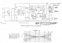
Probably something like thisI have an early 1950s preamP
R2 (grid) : 100K
R11 (grid) : 68K
R4 and R13 (cathode) : 2.2K
R1 and R10 (grid) : 1M
R27 (HT drop) : 100K
C1 and C9 (cathode) : 33uf
HT from the power amp at the octal socket, pin 3 should be 200V. How would I calculate the voltages I should be reading after R27, anodes at pins 2 & 5, and cathodes?
Mona
Attachments
Yes, but the anode voltages are 220K, not 100K. Also, R27 is 100K, not 10K.
I looked up the curves in the ECC40 datasheet, but I'm not sure I see which I would plot it on.
I looked up the curves in the ECC40 datasheet, but I'm not sure I see which I would plot it on.
Well, now I'm not sure I understand. Could you elaborate or link me an explanation? Thanks.
The two tubes have the same DC conditions, because all the resistors (and the supply voltage) are the same for both.
This means that the plate current is the same for both. So, this means we can use a trick to separate the two circuits
from having a common decoupling resistor by considering the 100k (R27) as two parallel 200k resistors.
Then we can split apart the circuit end of those 200k resistors, separating the two stages, because the voltage at that point
won't change, due to the symmetry of the circuit. Now we have two separate but identical circuits.
The power supply is 200V fixed. The DC resistance from there to either plate is 420k (the 200k decoupling resistor for that tube
plus the 220k plate resistor), ignoring the decoupling capacitor after R27. This is DC, so the capacitor is an open circuit.
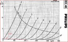
So, you can plot the DC load line on the tube curves as 420k, starting from 200V on the Vpk axis.
Then, since you know the 2.2k cathode resistor, you can plot the grid bias line, using the equation Ip = Rk x Vg.
For example, the point on the -1V grid curve is 1Vx2.2k, or 2.2mA. The point on the -2V grid curve is 2Vx2.2k, or 4.4mA.
Find where the curve formed by joining these grid bias points intersects the 420k load line, and that's the DC operating point.
See any tube manual if you haven't done graphical work like this before.
Last edited:
Yes, but the anode voltages are 220K, not 100K. Also, R27 is 100K, not 10K.
I looked up the curves in the ECC40 datasheet, but I'm not sure I see which I would plot it on.
Use the Ip vs Vpk curves. The grid voltage will be a parameter, giving the several curves on the graph.
Thank you for your patience and explanations. I am still somewhat new to the world of valves. I will take a look at this after the holiday!
That gives you this.Use the Ip vs Vpk curves. The grid voltage will be a parameter, giving the several curves on the graph.
Vk=1V , can do ,but Va=30V , very low.And not sure you can trust the graphs so low in a corner.
Mona
Attachments
You should be able to work it out from the Leak TL12 which was intended to supply this preamp. http://www.44bx.com/leak/Leak/tl12_cct.gif.
What is the voltage rating of C24?
What is the voltage rating of C24?
Last edited:
Yes, I had looked at the supply voltage discrepancy. On that same site, if you look at the information for the RC/PA/U, the supply voltage indicated is 450V- if I recall correctly.
The unit is intended to be coupled with, as you said, the TL/12 plus or the TL/25a. Both of these supply a voltage of 200V to the octal plug for the umbilical connecting the two units.
I don't have the unit in front of me at the moment as I'm getting ready to travel for the weekend but C24 was 8uf replaced with a 10uf when I recapped. (It still had the original 1951 Spragues in it!). I don't have the voltage of the cap listed in the spreadsheet I have on this computer, but I'm sure it's in my hand written notes somewhere. I'll check when I return.
Well, then you have Vk=2V and Va=70V. Acceptable 🙂Yes, I had looked at the supply voltage discrepancy. On that same site, if you look at the information for the RC/PA/U, the supply voltage indicated is 450V- if I recall correctly.
Mona
Attachments
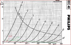
Well, then you have Vk=2V and Va=70V. Acceptable 🙂
Mona
Yes, I think this is probably right, if the supply is 450V.
That sounds closer to what the datasheets are saying. The only issue is that the supply voltage is not 450V, but rather 200V. This is indicated on the schematic for the TL-12/plus as well as the TL-25A. I could rewire the supply to 450V, taking it after the first stage filter in the power amp. I'm not sure this would be smoothed enough though as the schematic of rht power amps has another filter stage before the supply out through the octal plug. Also, it seems that the designer intended the supply to be 200V. Further thoughts?
Last edited:
200V is uncommonly low. Assuming all the caps can withstand it, I would bump up to 400V or more. R27 and C24 form a very heavy filter, so I doubt ripple would be a problem (assuming C24 is 10uF or more).
Yes, I thought 200V sounded low as well but I also recall reading in the literature on that website that these preamps were specifically designed to be paired with the TL-12 and TL-25 series power amps.
When I return I'll try raising the supply voltage. I'm running this into a TL25, which already has another preamp stage before the phase inverter.
When I return I'll try raising the supply voltage. I'm running this into a TL25, which already has another preamp stage before the phase inverter.
- Status
- Not open for further replies.
- Home
- Amplifiers
- Tubes / Valves
- ECC40 Voltage Question