Hello all.
I am inspired by the L'amp by Michael Rothecher and other valuable information in DiyAudio community.
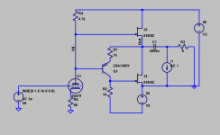
I simmulated a amplifier using;
2SK79 as a gain stage,
BJT as a phase inverter,
and Push Pull 2SK82 as a final stage.
SIT models are from Micheal's 2SK82 model and from Aumi's lab 2SK79.
This circuit topology have been used in my all tube 6FQ7 headphone amplifier for long time with good sound quality (smooth and natural, people say).
In this simm, the output power would be 14W max at 50v DC and 39W at 80Vdc . The Zo would be 1 ohm. 2SK82 Idle current is 0.8A-1A.
The THD is not good mainly because gain stage is simple single SIT.
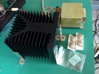
I gathered following stock parts to make this amp real;
big heat sink (120mmHx130mmWx150mmD),
2 pairs of 2SK82,
2SK79's,
trafo probably produce +/-40V DC,
and no 50VDC electrolitec capacitor on hand.
The power supply must be LR separated low ripple type, otherwise noise and crosstalk will occur.
I am hesitating to build this amp right now because of the power consumption. In Japan, after TEPCO Fukusima accident, No nuke is working and electricity charge have been rising . But I also think the sound may be very good. Is this a late comer?
How do you think?
I am inspired by the L'amp by Michael Rothecher and other valuable information in DiyAudio community.
I simmulated a amplifier using;
2SK79 as a gain stage,
BJT as a phase inverter,
and Push Pull 2SK82 as a final stage.
SIT models are from Micheal's 2SK82 model and from Aumi's lab 2SK79.
This circuit topology have been used in my all tube 6FQ7 headphone amplifier for long time with good sound quality (smooth and natural, people say).
In this simm, the output power would be 14W max at 50v DC and 39W at 80Vdc . The Zo would be 1 ohm. 2SK82 Idle current is 0.8A-1A.
The THD is not good mainly because gain stage is simple single SIT.
I gathered following stock parts to make this amp real;
big heat sink (120mmHx130mmWx150mmD),
2 pairs of 2SK82,
2SK79's,
trafo probably produce +/-40V DC,
and no 50VDC electrolitec capacitor on hand.
The power supply must be LR separated low ripple type, otherwise noise and crosstalk will occur.
I am hesitating to build this amp right now because of the power consumption. In Japan, after TEPCO Fukusima accident, No nuke is working and electricity charge have been rising . But I also think the sound may be very good. Is this a late comer?
How do you think?
Attachments

Have you checked:
1) How to set bias and balance - adjustable voltage sources? - since SITs have rather large tolerances even within the same rank group?
2) Power supply rejection, by putting an AC source in series with the power supply or bias supply?
3) What happens at clipping?
4) What happens at power-up
5) gate stoppers for SITs?
Lots of things to check in a simulation before you even start thinking of a real version... and unlike errors in the real world, it only costs some time.
Have you checked:
1) How to set bias and balance - adjustable voltage sources? - since SITs have rather large tolerances even within the same rank group?
2) Power supply rejection, by putting an AC source in series with the power supply or bias supply?
3) What happens at clipping?
4) What happens at power-up
5) gate stoppers for SITs?
Lots of things to check in a simulation before you even start thinking of a real version... and unlike errors in the real world, it only costs some time.
Thank you for the comment.
Yes, these are the points that need to be considered carefully before actual building. Tiresome business.
Followings are some thought about your questions.
1)Bias and Balance.
The bias is set by V5.
The value is twice of the operating point so that this can shut off the SIT.
DC balance depends on input voltage, Vd of first stage. this can be adjusted by various way, adjusting 2SK79 source resisitor might be the easist way to get best DC balance. AC balance depends on R1 and R2. If these are the same value, no problem.
2)Power supply rejection.
This probably be the biggest headache and cost.
Ripple rejection and also stabilization are crucial factor of a SIT amp. I think.
CLC filter needs big and custom made inductor or High cuurent high Voltage regulator. I prefer voltage regulator but may need to design it.
3) Clipping
This may not cause a big problem. According to simm. overdrive does not cause serious problems.
4)power-up
If bias voltage stabilized prior to B+ up, it may be OK.
Simply, unswitched rectifier works for this purpose.
5) gate stopper
Yes, SIT oscilates when the gate is driven by low impedance source.
--------------------------------------------------------------------------------
Tetsuo
2SK82 CIRCLOTRON shows good liniarity
Hello all
I have simulated various topology for making the best use of 2SK82 pair.
Because this 2SK79-2SK82 SEPP amp presented here needs a lot of adjustments of interdependent voltages and thus future long tweaking will be expected.
Finally I come up with the Circlotron class AB.
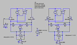
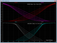
I simulated 2SK82 circlotron amp having only final stage,I also simulated 2SK1056 circlotron final stage. (Circuits are shown in fig.1)
The bias voltages of the amps are supplied from a step voltage generator.
Output voltages are usually checked to see their Fourier components, but I need instantaneously to see each distortion level on each stepped bias voltages.
So, I changed the rule to more direct method, Measure the liniarity.😀
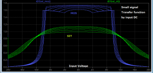
Measuring Liniarity is equal to measuring Differential Gain. if you use d(signal) function, it can show the DG.
Combining with DC analysis, you can see the liniariy very easily.
If signal is in flat DG region, it means no harmonics in the output signal.
The simulated liniarity,DG are shown in fig.2.
The drain currents are shown in fig.3.
Findings;
1. SIT circlotron has good linearity even low bias current. 😀
2. MOS circlrotron has higher gain but less linear than same idle current SIT.😱
3. DG is more direct and quick linearity measurement than Fourier analysis in LTSPICE.😀
I will try to build 2SK82 circlotron final stage supplied from regulated 20Vdc floating supply with 0.5A bias.
The estimated spec. is 18W/8ohm, DF 5, gain -6db, and Power consumption 50W stereo.
Tetsuo. 🙂
Hello all
I have simulated various topology for making the best use of 2SK82 pair.
Because this 2SK79-2SK82 SEPP amp presented here needs a lot of adjustments of interdependent voltages and thus future long tweaking will be expected.
Finally I come up with the Circlotron class AB.
I simulated 2SK82 circlotron amp having only final stage,I also simulated 2SK1056 circlotron final stage. (Circuits are shown in fig.1)
The bias voltages of the amps are supplied from a step voltage generator.
Output voltages are usually checked to see their Fourier components, but I need instantaneously to see each distortion level on each stepped bias voltages.
So, I changed the rule to more direct method, Measure the liniarity.😀
Measuring Liniarity is equal to measuring Differential Gain. if you use d(signal) function, it can show the DG.
Combining with DC analysis, you can see the liniariy very easily.
If signal is in flat DG region, it means no harmonics in the output signal.
The simulated liniarity,DG are shown in fig.2.
The drain currents are shown in fig.3.
Findings;
1. SIT circlotron has good linearity even low bias current. 😀
2. MOS circlrotron has higher gain but less linear than same idle current SIT.😱
3. DG is more direct and quick linearity measurement than Fourier analysis in LTSPICE.😀
I will try to build 2SK82 circlotron final stage supplied from regulated 20Vdc floating supply with 0.5A bias.
The estimated spec. is 18W/8ohm, DF 5, gain -6db, and Power consumption 50W stereo.
Tetsuo. 🙂
Attachments
If I am looking at your circuite right you are trying to use a single 20v floating supply ?
A circlotron needs 2 floating supplies per mono amp.
A circlotron needs 2 floating supplies per mono amp.
Woody, thank you for your comment.
Actualy there are two floating supplies per channel, The E, Voltage controlled voltage source has completely isolated input from the output.
Tetsuo
Actualy there are two floating supplies per channel, The E, Voltage controlled voltage source has completely isolated input from the output.
Tetsuo
- Home
- Amplifiers
- Solid State
- SIT amp simmulation, 2SK79+2SK82 push-pull