Hello. I'm new so nice to meet everyone. I joined here after seeing someone else with the same stereo post and get swamped with people that knew what they were talking about + were familiar with the parts the amp used, and other threads are highly technical, so figured it this was a good place to learn. My ability range is soldering, upgrading film and electrolytic caps, etc. But actual diagnostics is basically "I'm green". So, just go easy & please and understand I might not understand everything as it isn't 2nd hand to me yet.
OK, I have a MCS 3233 amp I've been restoring. Had one as a teen in the early 90's my dad gave me, and it was just a great amp then, that died many years ago and was tossed. About a year ago got tired of sub-par sounding "modern' amps and went old school again. Back in it now and have this 3233 and a parts unit. Have other gear, but this one is still favorite. While not the quietest at 0 volume, it's still a greatly musical and punchy amp + the sentimental value makes it my preferred go-to amp for daily duty. It's had all of it's electrolytic and film caps upgraded on power supply, tone, and amp board. Super Through mains, Nichicon FG power supply, and Elna Silmic II everywhere else. Tuner board was left alone though. Has Solen, Orange Drops, and mainly Vishay-Roderstein, and a 6 polystyrene in tone board replacing the factory ceramics there. Upgraded the on/off switch with an ALPS piece and better snubber, and recently replaced all the ceramics in the power supply that were complimenting a diode each with better ceramics as it was getting some excess noise at power up.
So far, it sounds much better than stock. I just love it despite being a 33 wpc.
Anyways, been buttoning everything up and thought it had DC offset pots on the amp board, but they turned out to be bias pots. I cleaned them up a bunch with Deoxit and are working smoothly.
1. I need advice/assistance with biasing properly, please.
2. DC offset is apparently controlled via a resistor? Right channel is right around 16mv, but left channel shows a -64mv. I'm guessing either a resistor failed or is at the bottom end of drift. Most film caps were 10% tolerance but I think some parts are 20% tolerance. Anyway to easily trace where the DC offset resistor might be so I can replace them?
Amp board is small and basic with minimal going on, so just hoping it can be an easy "find Waldo" scenario. Worse case, I'll replace all the resistors in one go though the color bands are kinda tricky with red and orange almost being identical, and other resistors tested have been within 10% of each other, so worse case I can ballpark it based of parts unit resistors if colors can't be correctly identified.
Thanks. And again, nice to meet everyone that may or may not comment.
I'm not familiar with the amp but I would doubt there is a problem with DC offset given the values you quote.
Without seeing a circuit... DC offset is primarily determined by the 'balance' of the DC conditions in the input stage of the power amplifier and that comes down to the basic design and the matching of the semiconductor characteristics. Offsets of -/+100 mv are acceptable (and normal on older equipment when it was less fashionable to worry over such things) and so I don't think you have a problem with any failed or out of spec components.
Bias is critical because an incorrect setting could lead to thermal runaway and major damage... circuit depending. With no details available (unless you have a manual) then you need to set it on the safe side which would be around perhaps 50 milliamps. You measure the current by measuring the volt drop across the low value emitter resistors connected to the output transistors and calculating the current using ohms law and the resistor value. If the output stage is what is known as a CFP type (this has the emitters going to the supplies and the speaker output from the collectors) then the recommended current could be as low as 10 milliamps or so.
Bias is critical because an incorrect setting could lead to thermal runaway and major damage... circuit depending. With no details available (unless you have a manual) then you need to set it on the safe side which would be around perhaps 50 milliamps. You measure the current by measuring the volt drop across the low value emitter resistors connected to the output transistors and calculating the current using ohms law and the resistor value. If the output stage is what is known as a CFP type (this has the emitters going to the supplies and the speaker output from the collectors) then the recommended current could be as low as 10 milliamps or so.
I'm kinda following what you are saying. Consider me a 4 year old learning how to spell Dog while you just graduated college 😀 I know it has 4 emitter resistors .33 @3w, where it seems 2 of them are per channel. As far as the rest, I'm sorta lost. I read elsewhere on biasing, but w/o pics it was hard to follow as that person skimmed over how he was jumping wires to emitters or I think that's what he was saying.
Use your meter to measure the voltage between ground and those resistors. That will give a good clue as to the type of output stage configuration. You just measure to one end of each resistor (doesn't matter which) and tell us what you see. And be careful, one slip of the meter lead and it all goes bang.
So that is just two readings. What do you see ?
So that is just two readings. What do you see ?
Amp board is labeled L/R, so probed furthest left resistor with 29-30mv; probed further right emitter resistor and same 29-30mv. It was bouncing between 29-30.
That sounds like a standard EF (emitter follower) stage and so with 0.33 ohm resistors, biasing to around 50 milliamps should be a safe value.
To set the bias you have no speakers connected and no signal present. Let the amp warm up fully and then adjust for around 20 to 24 millivolts MEASURED ACROSS either of the 0.33 ohms.
The bias current will never be totally stable and will alter with temperature.
To set the bias you have no speakers connected and no signal present. Let the amp warm up fully and then adjust for around 20 to 24 millivolts MEASURED ACROSS either of the 0.33 ohms.
The bias current will never be totally stable and will alter with temperature.
Just so I'm understanding "Measured Across", I probe ground and then probe a resistor end, adjust pot slightly, check value again? Then repeat until around a 20-24mv is achieved? Or are you suggesting I probe the end of each resistor or something?
Last edited:
Across means across 🙂 One lead on one end of the resistor, and the other lead to the other end. The reading on the meter could be either positive or negative depending on which way around you connect, but that doesn't matter in this case.
It might be easier and safer for you to tag wires to the resistor and connect the meter to those. Then you can monitor the current and adjust it.
It might be easier and safer for you to tag wires to the resistor and connect the meter to those. Then you can monitor the current and adjust it.
Thank you so much for being crazy fast with responses and clarifying. I'm going to go and carefully adjust right now 🙂
BTW, I take it a little more heat will be generated at this 50 mA range? This unit has a basic 3 walled heat sink with no fins. Been wanting to mod-in a better heat sink I have laying around or put a fan in. Regardless, thank you so much!
BTW, I take it a little more heat will be generated at this 50 mA range? This unit has a basic 3 walled heat sink with no fins. Been wanting to mod-in a better heat sink I have laying around or put a fan in. Regardless, thank you so much!
More or less heat depends on what the original settings were in the first place. Its always best to play safe, particularly when its an unknown. In fact, if you rig up wires to monitor the current then you can try listening to it from zero bias upwards. You'll find that even from a couple of milliamps up and there is probably no audible change.
The important points are that is must not run to hot when its all back together with the top on and that the current doesn't rise and keep rising (destructively) when playing loud. When you cut the audio the current should fall back to around the set value fairly quickly... within 30 to 60 seconds.
The important points are that is must not run to hot when its all back together with the top on and that the current doesn't rise and keep rising (destructively) when playing loud. When you cut the audio the current should fall back to around the set value fairly quickly... within 30 to 60 seconds.
Set left at 23.6 and right at 23.7~23.6.
Thanks again Mooly. You made my night. Have a good one mate!
Thanks again Mooly.
You made my night. Have a good one mate!The important points are that is must not run to hot when its all back together with the top on and that the current doesn't rise and keep rising (destructively) when playing loud. When you cut the audio the current should fall back to around the set value fairly quickly... within 30 to 60 seconds.
Excellent points I'll put to heart. This unit stays under 10w when normal listening, but I'll run near clipping later on and see what it's doing. I didn't feel any heat increase after adjusting. I noticed earlier when (embarrassingly) thought they were DC offset pots, the heat increased fairly quickly.
Wish I'd joined here sooner as the other site I spend much time on, wouldn't offer this level of help. Again, so grateful!
This seems to be an off-brand, US-only model. There's an old thread here about MCS 3233 problems which illustrates how not to mess with amplifiers, as the OP just thought he'd set a bias of 125 mA based on a generalised type of design or forum chat, I guess. As Mooly's caution suggests, this proved to be a bad idea.
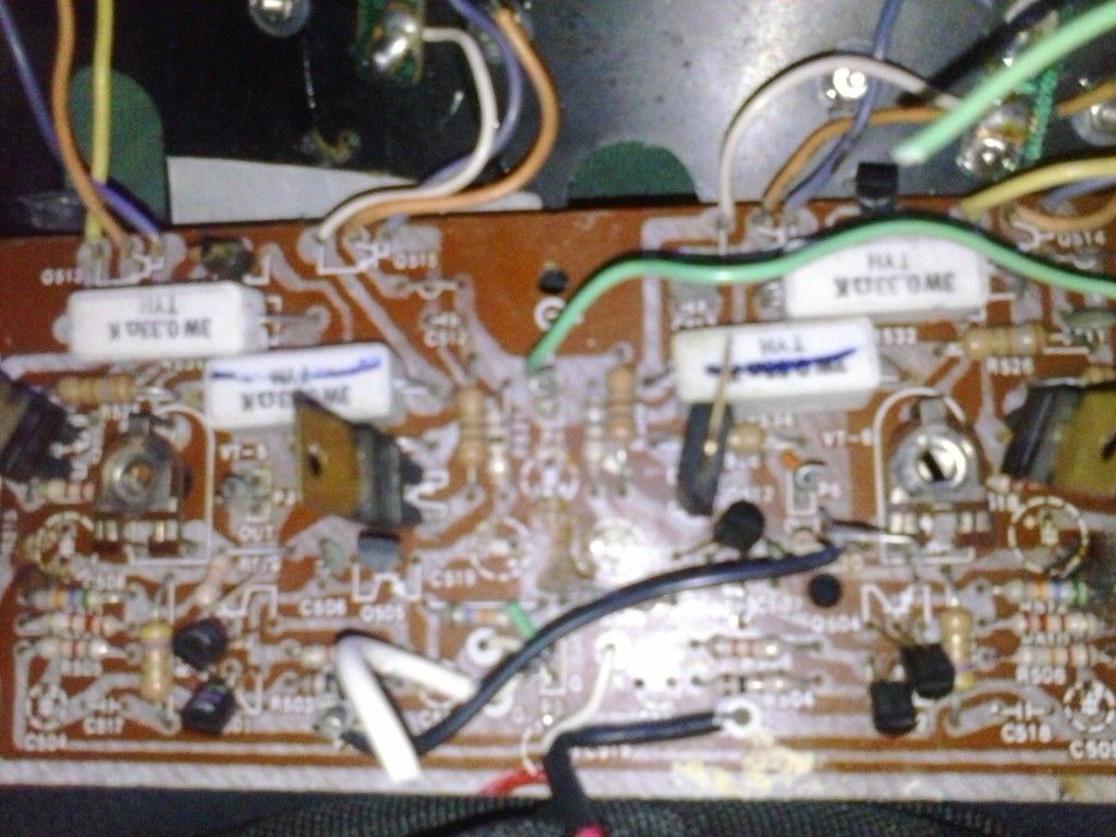
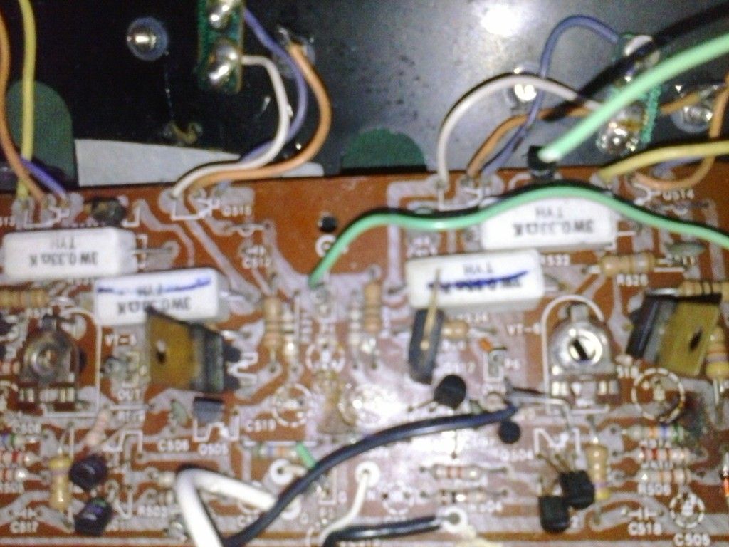
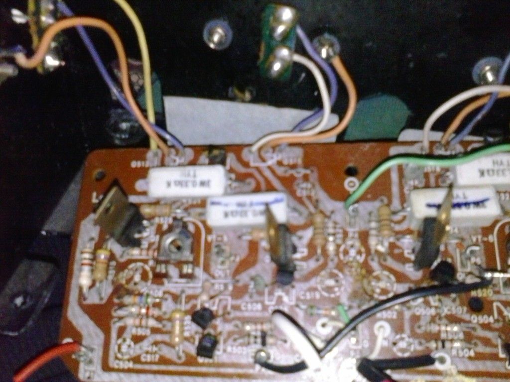
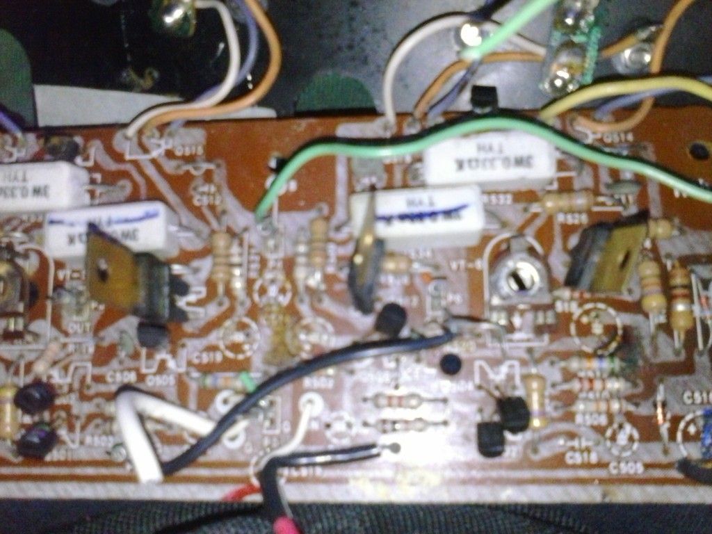
Without some form of schematic or high res. pics, top and bottom of the power amplifier PCB, it could be risky offering specific advice about this model. As you say it seems a simple design, why not spend a little time tracing out the amplifer circuit, adding the parts values and posting it here. We can be more helpful when we know what you are talking about in familar terms and diagrams: http://www.diyaudio.com/forums/solid-state/15720-amp-died-while-biasing.html
Still, assuming this web pic is indeed right for the model, that heatsink looks to be very small, even for a 30W amplifier. So it does appear to be CFP design since they usually idle cool with low bias like 10-15 mA - hence the bad idea problem.
Last edited:
This seems to be an off-brand, US-only model. There's an old thread here about MCS 3233 problems which illustrates how not to mess with amplifiers, as the OP just thought he'd set a bias of 125 mA based on a generalised type of design or forum chat, I guess. As Mooly's caution suggests, this proved to be a bad idea.
Without some form of schematic or high res. pics, top and bottom of the power amplifier PCB, it could be risky offering specific advice about this model. As you say it seems a simple design, why not spend a little time tracing out the amplifer circuit, adding the parts values and posting it here. We can be more helpful when we know what you are talking about in familar terms and diagrams: http://www.diyaudio.com/forums/solid-state/15720-amp-died-while-biasing.html
Still, assuming this web pic is indeed right for the model, that heatsink looks to be very small, even for a 30W amplifier. So it does appear to be CFP design since they usually idle cool with low bias like 10-15 mA - hence the bad idea problem.
I saw that post! It only appeared in search engine though after adding the 3055/2955 w/o any mention of what it was, and is the reason I joined up here. I've read every post I could find on this stereo, so it was a surprise seeing something new, and this forum typically doesn't get hits in the US as I've rarely seen it show up before. I was reading all these brilliant minds respond to his issue and I knew I had to join up! 😛 Also, he stated his transformer was scalding hot. Mine is barely warm, so maybe he had something else going. Plus, I doubt he had everything recapped, so it's possible something else let go or his specs were way out of wack, and it was coincidental. After adding just the electrolytic caps, the tone board started acting up and quit about 30 minutes later. Everything turned on, no sound, and no FM tuning needles worked either, despite their pots being on the tuner board. Double checked everything, and nothing was installed incorrectly, and all solder was cleanly applied, so just luck of draw.
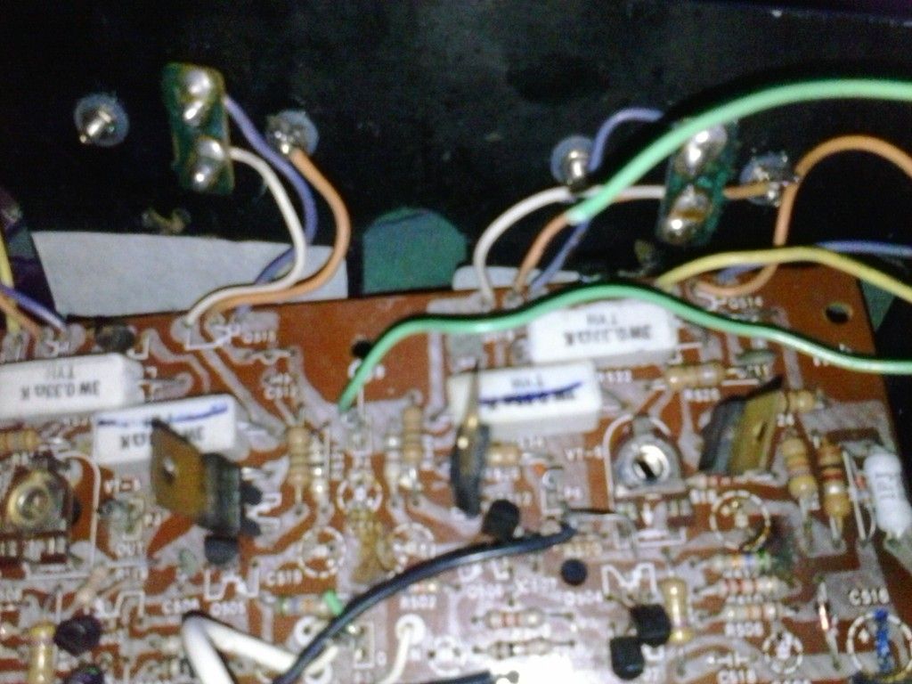
Yes, that's a rough looking gut shot, but is the same as mine. It was made by a US company called "Arvin" that had been around since the early/mid 1900's. They farmed out the build work in Taiwan, and these were sold apparently ONLY under the MCS branding for the JCPenny department store here in the US, probably to compete with Sharp's "Optonica" brand that I think Sears sold, as well as Pioneer, Realistic, etc. as they borrowed build and styling cues heavily from many of those. Many think these were made by Technics and even Panasonic, but they weren't (maybe mid/late 80's "MCS" were, but not these). There were a handful of these "Arvin" units made going up to I think 45 wpc, then they went with NEC rebadges for the high-end MCS. The 3233 and 3245 are gems so to speak and sound bigger than they are when paired with proper SPL speakers. 3233 is tad noisy at idle with headphones, with some tone board noise creeping in, but otherwise very musical and punchy. Bass around 35 hz sine wave (with mine after upgrades) can easily hit a 114db with a single 95 SPL 15" woofer in a 3-way cab, so you can see why I like it 😉
Anyways, I was told elsewhere 30v is the max 3055's are supposed to be at. Factory had this at nearly 33v. What's really confusing me though, is why does it get hotter at IDLE with less voltage? At 31.5v, I could actually feel the heat rising which took me for a loop. I risked life and limb and touched the heat sink's top edge, and noticed right away the 2955's were HOT, and the 3055's took longer to heat up. The edge of heat sink was almost too hot to keep finger on. I quickly put it back to as close as the factory had it, and it was showing 33.3v, so figure they had it at least 33v from factory. Temps immediately lowered too. I find this very perplexing as PC equipment (GPU and CPU) both get hotter with even minor voltage bumps during overclocking. This actually gets hotter with less at idle. But this is why I joined here, as you folk clearly know your amplifier components and have answers!
Can it be pulling more current at less voltage? I was also thinking, maybe this was a cheap, sneaky roundabout way they went about keeping a basic heat sink in place as idle temps were lower with more voltage? Does it scale the same way? i.e. less heat at higher volume with a touch more voltage? Another thing that's confusing is if the 3055 is rated at 40 w (I've seen 50w quoted too, so dunno which is correct?), and this amp is rated at 33 wpc, where'd the last 7w go? If higher voltage = less wattage, I don't understand that 😕
I have several nice, finned heat sinks floating about. Although working with aluminum and a dremel is a royal pain, I could conceivably make a better one for this if it must run at 30v idle or bolt sections onto existing plate and use thermal compound.
I can take a decent top shot of whats there, and list ALL cap values, and say emitter resistors, but the tiny resistors will be tougher as the coloring they used is difficult to detect the actual shade in some cases i.e. orange and red look a LOT alike, and some colors aren't easy to tell what it even is. I can also post a less cluttered shot of the parts board amp section as all caps are pulled, but you can see the resistors easier and the top tracing marks. And a bottom shot will have be of the parts board as it's too much unsoldering to lift present board out for bottom-shot. Could also lift a leg on parts board to get resistor values, though I've some drift between both unit's power supply resistors, where oddly enough one unit was consistently high and other low; 218 ohm vs. 222 ohm for example, where I'm guessing 220 was the value needed.
For what it's worth, if the 23.6 mv I set both channels at is seemingly "safe", I'm perfectly content with that. Actual transistors are showing 32.3~32.5v and barely warm idling. BUT, if the voltage is actually too high right now and these indeed need to be closer to 30v, I'll do all the pictures and post, and edit image giving as many values as possible within image.
I'll just wait for the word, otherwise I'm content with where it's at. Originally went in looking to make sure DC offset was OK, made mistake about pots, read up briefly on biasing, then figured it'd be nice if it was properly biased, hence the journey landed here

Last edited:
what are the emitter resistor values?.......................For what it's worth, if the 23.6 mv I set both channels at is seemingly "safe", I'm perfectly content with that. Actual transistors are showing 32.3~32.5v and barely warm idling.................
The Vre and Re determine the output bias current.
That bias current times the supply rail voltages define the power that must be dissipated. That is where your temperature rises come from.
Have you identified your output stage topology?
Is it EF for driver and for output, or CFP combination of driver+output?
It makes a big difference to the Vbias value that should be set.
An EF driver and output will have a NPN driver and an NPN output between +ve supply and output and a PNP driver and a PNP output between -ve supply and output.
A CFP will have an NPN driver + PNP output in the +ve half and a PNP driver +NPN output in the -ve half.
.
Last edited:
Anyways, I was told elsewhere 30v is the max 3055's are supposed to be at. Factory had this at nearly 33v. What's really confusing me though, is why does it get hotter at IDLE with less voltage? At 31.5v, I could actually feel the heat rising which took me for a loop. I risked life and limb and touched the heat sink's top edge, and noticed right away the 2955's were HOT, and the 3055's took longer to heat up.
I think that somewhere in all that, is that what you are observing is just the power supply dropping as you turn the bias current up. Thats normal, the extra load pulls the voltage down a bit but that effect soon levels off. The power supply in that amp will deliver a couple of amps or more continuosly and the voltage wouldn't fall much further.
If you have 30 volts across each transistor and a current of 50 milliamps flowing then that is 30*0.050= 1.5 watts per device. Not so much. 35 volts say and its 1.75 watts. Increase the bias to 100ma and you are in the region of 3 watts per device. Thats when things start getting hot.
Commercial products are made down to a price and cost savings made where possible. The theoretically correct or optimum bias for the amp is probably one that could not be supported by the available heatsinking/ventilation and power supply.
what are the emitter resistor values?
The Vre and Re determine the output bias current.
That bias current times the supply rail voltages define the power that must be dissipated. That is where your temperature rises come from.
Have you identified your output stage topology?
Is it EF for driver and for output, or CFP combination of driver+output?
It makes a big difference to the Vbias value that should be set.
An EF driver and output will have a NPN driver and an NPN output between +ve supply and output and a PNP driver and a PNP output between -ve supply and output.
A CFP will have an NPN driver + PNP output in the +ve half and a PNP driver +NPN output in the -ve half.
.
Emitter resistors are .33 @3w; there are two per channel, so four total.
I honestly have no idea if EF or CFP as I have no idea what those are. When you are talking Vre, ve, etc. I'm not sure how to identify those either. I've looked at ON SEMI transistors' spec sheets and have seen those values listed, but am unaware what part of the transistor they occupy.
These are the best pics I can take on short notice. Phone camera isn't greatest and my better cam has no batteries, sorry, but you can see the white paths at least for most part that exit emitter resistor and enter transistors and the 4 things with the copper metal tabs (no idea what they are called). 2955's are center back of black heat sink (purple and white wire, orange to outer shell). 3055's are on opposing ends (yellow and purple wires, orange wires to shell/case).
If you have 30 volts across each transistor and a current of 50 milliamps flowing then that is 30*0.050= 1.5 watts per device. Not so much. 35 volts say and its 1.75 watts. Increase the bias to 100ma and you are in the region of 3 watts per device. Thats when things start getting hot.
Commercial products are made down to a price and cost savings made where possible. The theoretically correct or optimum bias for the amp is probably one that could not be supported by the available heatsinking/ventilation and power supply.
Can you explain how milliamps is read or derived from these? My multimeter was detecting anything.
When you say 1.5watts or 1.75watts per "device", I'm not understanding what "device" represents.
Unit has a 290w rating on back and it has a 3 amp fuse. Power supply is fairly heavy for what this is. If I improved heat sink and added a fan (fan itself can keep a unit powering four 3-ways with 12" woofers several hours straight at +10 bass with loudness on cool from experience with prior amp in my teens), would there be a benefit at setting this so 30~30.5v is seen at the transistors?
So you are saying the voltage drop is more load pulling it down? If it leveled, are you suggesting voltage would increase?
I can live with where it is now, but if there's a touch of performance to be had assuming I can dissipate the heat (which I can), I'd prefer to have it where a proper unit running these transistors and decent cooling would be at.
Can you explain how milliamps is read or derived from these? My multimeter was detecting anything.
Take the voltage.. Earlier you said 29mV
Divide that by the resistance.. .33ohms
so.. .029V divided by .33ohms = .0878 which is 88mA
I think I'm correct. Thats my formula.
Although I dont see 29mV being a problem. It was recommended earlier to drop it to 25mV. But I think your bias is close enough if your getting 29-30mV from emitter resistor.
- Status
- Not open for further replies.
- Home
- Amplifiers
- Solid State
- Biasing MJ2955 and 2N3055