I was ebaying for a little chinese circuit board with delay relay that will turn on the anode voltage supply half a minute after the power is on. You know, automatic standby switch. For some reason, all the timer modules are cyclic and (singing in Bono voice) I still haven't found what I'm looking for.
What do you use for automatic B+ delay? Apart from standby and progressive on\off switches.
What do you use for automatic B+ delay? Apart from standby and progressive on\off switches.
Last edited:
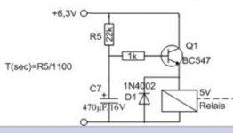
Just a 555 delay circuit which drives a relay through a BC640. The 555 gets its voltage from heater.
I was ebaying for a little chinese circuit board with delay relay that will turn on the anode voltage supply half a minute after the power is on. You know, automatic standby switch. For some reason, all the timer modules are cyclic and (singing in Bono voice) I still hasn't found what I'm looking for.
What do you use for automatic B+ delay? Apart from standby and progressive on\off switches.
Where would you place it? Before or after the PS filter caps? Would you charge the filters before applying the B+?
I'm somewhat anal about digital noise getting into the B+ rail. Scan the archives over on AA's Tube DIY "board", where I discussed a scheme using an Amperite thermal delay relay and a cross connected "standard" relay. That setup is purely electromechanical and (obviously) noise free.
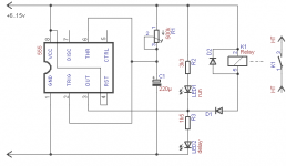
As simple as this
... or even simpler, installing a B+ switch with 300K or so across.
I'm somewhat anal about digital noise getting into the B+ rail. Scan the archives over on AA's Tube DIY "board", where I discussed a scheme using an Amperite thermal delay relay and a cross connected "standard" relay. That setup is purely electromechanical and (obviously) noise free.
... or even simpler, installing a B+ switch with 300K or so across.
Thermal delays have their uses, but care sometimes need to be taken in the event that power is removed and then reapplied before the device has cooled.I'm somewhat anal about digital noise getting into the B+ rail. Scan the archives over on AA's Tube DIY "board", where I discussed a scheme using an Amperite thermal delay relay and a cross connected "standard" relay. That setup is purely electromechanical and (obviously) noise free.
The 555 timer circuits shown above are clean, noise wise. Firstly the device is a simple analogue timer, and secondly the only possible noise that it can add is at the instant that its output switches (i.e. before the amplifier is able to amplify anything). After that it is an entirely static device in these configurations. In these circuits it will create no more noise than a thermal timer, but with less heat.
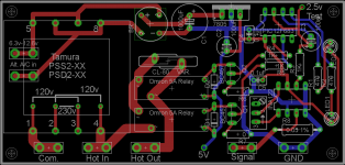
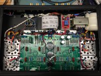
My timer. It switches on the b+ transformer in my GM70 amp. The pic micro is programmed for a 10 second delay on the first relay then 1 second to the second relay (slow start) then it waits 1 second and monitors the current through the GM70 via 0.05 ohm resistor. The voltage at the 0.05 ohm resistor is amplified by the INA122. The INA122's output is varied via the pot and I set it at 2.5 volts for the pics A/D converter. It will shut down in either an over or under current state.
Attachments
Thermal delays have their uses, but care sometimes need to be taken in the event that power is removed and then reapplied before the device has cooled.
The 2 relay setup I described turns the thermal relay's heater off, immediately after it trips. That's good for both cooling down early and extending service life. The "standard" relay is wired to be self latching and thermal relay de-energizing.
If the entire unit is powered down shortly after the thermal relay trips and immediately reenergized, signal tube heaters will be hot and filter caps. charged up. There's little, if anything, that can go wrong under those circumstances.
I'm somewhat anal about digital noise getting into the B+ rail. Scan the archives over on AA's Tube DIY "board", where I discussed a scheme using an Amperite thermal delay relay and a cross connected "standard" relay. That setup is purely electromechanical and (obviously) noise free.
How would a 555 in monostable mode cause any sort of "digital" noise? 😕
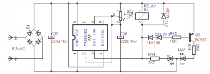
Or this one, using a single dual cathode red-green LED...
Btw, what's the point of all those leds? I mean, you could just wire the output through a resistor to base of a PNP transistor, which acts as a switch for the relay.
Last edited:
I wondered... That is exactly how I designed one using the VLS631 delay tube.The 2 relay setup I described turns the thermal relay's heater off, immediately after it trips. That's good for both cooling down early and extending service life. The "standard" relay is wired to be self latching and thermal relay de-energizing.
Btw, what's the point of all those leds? I mean, you could just wire the output through a resistor to base of a PNP transistor, which acts as a switch for the relay.
You can drop the LEDs, they are there only to show the delay/run status. The extra transistor in the second circuit is for the common cathode duo-LED, which cannot be driven by the 555 alone.
The 555 can drive most relays on its own, no need for an extra transistor. The voltage at its output is 2/3 of the supply voltage - that means you can use a 5v or 6v relay with a rectified 6.3vAC (8vDC) supply, or a 12v relay with a voltage doubled 6.3vAC supply.
Hi 12E1
Your picture looks like an 811A so I'll ask the question to you. With an 811A or 572B (the real one, the transmitting triode) is it necessary to delay the B+ as long as the grid voltage is applied after the B+. At 0V grid there is very little current from the plate or grid.
Your picture looks like an 811A so I'll ask the question to you. With an 811A or 572B (the real one, the transmitting triode) is it necessary to delay the B+ as long as the grid voltage is applied after the B+. At 0V grid there is very little current from the plate or grid.
Ive recently retrofitted my VR-110 amp with timer delay circuit purchased from Amzn (https://www.amazon.com/gp/product/B0126WT5QO/ref=oh_aui_detailpage_o04_s00?ie=UTF8&psc=1) and double the cap value in order to extend timer delays upto ~90sec (default ~30sec). For me I wanted to prolong the life of expensive output tube so switched B+ is only feeding to output tranny. Only other modification was adding 0.01uF, 1000v cap for switch from arcing. It's been working reliably for last few weeks so only time will tell how long the relay will last.
Attachments
- Status
- Not open for further replies.
- Home
- Amplifiers
- Tubes / Valves
- B+ delay timer module