I'm in the process of building a small aluminum anodizing setup. I need an adjustable constant current supply that can put out between a couple amps up to 40 - 50 Amps at around 15VDC. I've found many designs able to put out 5 amps but nothing high current. Does anyone have any schematics for such a unit?
Can you just scale up a 5A unit ?
Since you are not listening to your aluminum ... why not a scaled up
simple unit (below).
I'll add a driver for paralleled series BJT's. (one humungous darlington) 😀
At low voltage ... an MT-200
can pass 10A-15A. So , pretty much half a slewmaster at 15V can
pass 40A+ ...... see ?
OS
Since you are not listening to your aluminum ... why not a scaled up
simple unit (below).
I'll add a driver for paralleled series BJT's. (one humungous darlington) 😀
At low voltage ... an MT-200
can pass 10A-15A. So , pretty much half a slewmaster at 15V can
pass 40A+ ...... see ?
OS
Attachments
I tried to scale up a design similar to that in LT spice and was coming up with some wonderful oscillators. I wasn't using a LM317 to regulate it. Just an op amp. That's likely where my issues were coming from. I'll play with this and see what I can come up with. Thanks.
I tried to scale up a design similar to that in LT spice and was coming up with some wonderful oscillators. I wasn't using a LM317 to regulate it. Just an op amp. That's likely where my issues were coming from. I'll play with this and see what I can come up with. Thanks.
Take the op-amp supply separately from another 7815 running off the
unregulated supply.
use old parts .... 741's and 317's , these don't have the bandwidth to
cause HF oscillations.
I'll draw one up using that circuit if you can wait.
PS- I actually break the FB loop and do a phase margin test at freq. to test these PS's.
OS
Last edited:
Take the op-amp supply separately from another 7815 running off the
unregulated supply.
use old parts .... 741's and 317's , these don't have the bandwidth to
cause HF oscillations.
I'll draw one up using that circuit if you can wait.
PS- I actually break the FB loop and do a phase margin test at freq. to test these PS's.
OS
That would be great. I've got rails of LM224s and LM317s to work with.
I've always wondered why constant current sources always seem to have a voltage adjustment? Is this an actual regulation circuit or a high limit?
MJ15003/4 would do.
Two, or three, or maybe four, of these 20A, 250W devices should survive the continuous duty.
Two, or three, or maybe four, of these 20A, 250W devices should survive the continuous duty.
MJ15003/4 would do.
Two, or three, or maybe four, of these 20A, 250W devices should survive the continuous duty.
I was thinking of Mosfets if they could be controlled properly. I've got a bunch of IRFZ44s and IRFP240s. They might stand up better to accidents.
If the supply is actually C.C., accidents should always be benign. At this level of voltage, BJT's have no secondary breakdown issues, they can be used to their full power with proper heatsinking.I was thinking of Mosfets if they could be controlled properly. I've got a bunch of IRFZ44s and IRFP240s. They might stand up better to accidents.
For heavy, dirty jobs like electrochemistry, the last thing you want is something delicate, accurate and complicated, ie. not the example given in #2.
In fact, it can be pretty simple and yet perfectly effective, I think I have an example of such a supply in my files, just give me a little time to locate it.
Otherwise, I will sketch something suitable, it isn't really difficult if you take care of a few essentials.
If the supply is actually C.C., accidents should always be benign. At this level of voltage, BJT's have no secondary breakdown issues, they can be used to their full power with proper heatsinking.
For heavy, dirty jobs like electrochemistry, the last thing you want is something delicate, accurate and complicated, ie. not the example given in #2.
In fact, it can be pretty simple and yet perfectly effective, I think I have an example of such a supply in my files, just give me a little time to locate it.
Otherwise, I will sketch something suitable, it isn't really difficult if you take care of a few essentials.
Any help is much appreciated. Thanks.
You said you wanted voltage regulation , too.
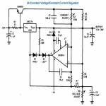
Just think of a big audio amp CCS , with a over-sized current shunt (below).
Circuit achieves constant current over wide range of terminal voltages
They use these for LED grow lights/street lights.
It can be a BJT or MOSFET , The FET will need to burn up the Vgs (less
output voltage). A 3 transistor circuit would do for a "dirty job".
OS
Attachments
You said you wanted voltage regulation , too.
Just think of a big audio amp CCS , with a over-sized current shunt (below).
Circuit achieves constant current over wide range of terminal voltages
They use these for LED grow lights/street lights.
It can be a BJT or MOSFET , The FET will need to burn up the Vgs (less
output voltage). A 3 transistor circuit would do for a "dirty job".
OS
I think I worded that wrong. The process needs around 15 volts to start to conduct through the acid solution. Voltage doesn't need to be regulated. Current does change significantly through the process and needs to be regulated though. As the aluminum surface starts to change state the current will drop and slow the process.
Well , then the "down an' dirty" monster CCS is just the ticket.
I'd go MT-200's and some of those 50W /20R softstart resistors.
Things you already have..... 🙂
OS
I'd go MT-200's and some of those 50W /20R softstart resistors.
Things you already have..... 🙂
OS
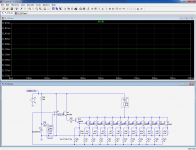
I think I'm doing something wrong. I've drawn this in LTSpice and seem to have a wonderful 6.562V voltage regulator.
I have a 2000VA 16-0-16 transformer so I could get 45VDC 60A from it so mosfets are a possibility too.
I have a 2000VA 16-0-16 transformer so I could get 45VDC 60A from it so mosfets are a possibility too.
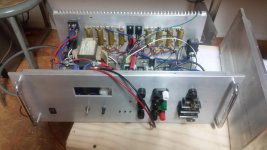
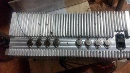
You're suggesting something like this? This is my bench supply. I like to use steel can TO3s in case I blow one, but have never managed to do that with this thing.
Yes , It looks like they do it in a similar way ... are they 2 big mosfets (or drivers) in
the middle ?
Don't worry , I am on the first 317 based circuit now. I simulated the
simple ones and they oscillate up at >20A.
I'll find one that will NOT be picky about models/components.
OS
Those are mjl21194 drivers in the middle. That was a project I started 10 years ago. It runs but I never had a chance to finish the voltmeter or chassis.
I've been messing around with little result this evening. I just stumbled across this design and it actually looks like a good starting point. Feed the output into the base of a darlington array and hook the adjust to the output of the darlington array. I'll mess with this in the morning.
Attachments
Last edited:
@ AndrewT (or others)... (O/T apologies)
Mains earth question, maybe you could help me.
A chassis which is tied to signal ground has floating supplies coming into it. They are filtered RF common to this chassis, then tied to it at the other end. The supply chassis, cores, mains and conduit are common to mains earth.
The amp chassis is biting me and I want to keep it as a signal shield. I'm happy to throw a stake out the window if it helps my cause, or use an outer case if I can isolate the inputs but I'd rather drain it if I can do it cleanly.
How much impedance can I put before it to PE? Should I put the easement by the signal reference and run it back with the rails?
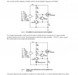
Here is a simple and reliable circuit, adjustable from 0 to ~50A.
The opamp can be any type including ground in its input range, LM358, etc
Thanks Elvee. This looks like it should work. I think I'll need to raise the supply voltage as the process requires 15VDC to conduct current. Is R24 and R29 correct? Is Q12 acting as a driver and an output?
- Status
- Not open for further replies.
- Home
- Amplifiers
- Power Supplies
- High Power Constant Current Power Supply Designs