Hey all,
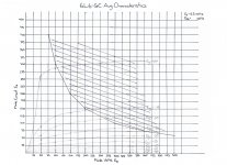
I re-drew the plate curves for a 6L6GC tube for a screen voltage of 350V, because I couldn't find any, and then followed Merlin's steps to draw a load line for a push-pull output stage with 370V plate voltage and 4200 ohm load.
Now, I've noticed a few things with this transformer.
1. The point where the line moves from class A to class B happens fairly early (it's heavy to the right).
2. The Ipeak where the class B load line touches the Eg=0 curve is at 280mA. Is that out of the ball park for a 6L6GC? Wouldn't I need a pretty beefy power transformer to supply that kind of current?
3. The load line crosses just slightly above the knee of the curve. Is this okay for a guitar amplifier?
Ideally, I'm thinking that for this plate and screen voltage, I'd like a load around 5000 ohms that can handle around 50 watts, but I'm finding output transformer selection somewhat limited within a budget here in Canada.
Could anyone out there quickly check the graph and share their thoughts or advice for a beginner?
Thank you in advance.
Dave
Attachments
The PT can be sized by the idle current plus some margin (say 20%) for good regulation, or if you like a saggy supply, less or no margin.2. The Ipeak where the class B load line touches the Eg=0 curve is at 280mA. Is that out of the ball park for a 6L6GC? Wouldn't I need a pretty beefy power transformer to supply that kind of current?
Certainly, for guitar amps, the load lines are often above the knee and way above the Pdiss line, but it depends on how hard you want to run the tubes and how much power you want to get out of them.3. The load line crosses just slightly above the knee of the curve. Is this okay for a guitar amplifier?
The chart you showed isn't quite right, the curves should be a bit higher. To save you time in the future, you can use this handy tool to work out the load line.Could anyone out there quickly check the graph and share their thoughts or advice for a beginner?
The PT can be sized by the idle current plus some margin (say 20%) for good regulation, or if you like a saggy supply, less or no margin.
Current being the sum of idle currents for both tubes in my push-pull stage, plus the idle currents for all of my preamp tubes? I have a couple 12AU7s in there that bring the total current demands up ever so slightly.
The chart you showed isn't quite right, the curves should be a bit higher. To save you time in the future, you can use this handy tool to work out the load line.
You're a saint.
That's correct.Current being the sum of idle currents for both tubes in my push-pull stage, plus the idle currents for all of my preamp tubes? I have a couple 12AU7s in there that bring the total current demands up ever so slightly.
I have never been called that before...😀You're a saint.
Follow up question. When picking an output transformer, how important is the power rating? For cost reasons, I'd like to get an OT with a power rating of 35 watts, but my design is slightly higher. There's a 50 watt version, but it's more expensive. Will a slightly under rated OT matter, and if so, what effects will it have on the amp (sound, heat, insulation breakdown, etc)?
You can of course play at a lower volume or simply roll off more of the lows, which allows the OPT to handle more power. Some even prefer to use undersized OPT's for their builds, but YMMV.
Just a small point, generally the beam pentodes/tetrodes tubes like the 6L6 and 6V6 will have much sharper knees like the top load line in your OP and the bottom load lines are more like true pentodes like the EL84 and EL34, with much more rounded knees. Some methods have you setting the load line to intersect the middle of the knee for the 6L6 curve, but as jazbo8 said, you can push them hard or back off.
Last edited:
Important tio keep in muind that the choice of plate curves is based what your power supply voltage will be at full power output...
If your screens are REGULATED at a fixed voltage then your good to go....
If not, then consider the voltage your screens will dip down to at full power output when selecting the proper plate curves, ie plate curves based on the SCREEN voltage you end up with at full power output...
Also if the plate voltage dips at fullpower output, then you need to shift the Load-Line to the left to end up at the proper point at full power output....
Basically disregard the idle voltages when doing the Load-Line analysis, else you will end up with much higher power outputs durring calculations..
This is why a full power supply analysis is required first...don't forget to include screen currents that get out of control even before you get to 0-Bias.....
Last edited:
The power transformer I'm looking at is the Hammond 272FX. I'm gonna run some numbers here as a sanity check.
The datasheet quotes a no load voltage of 654.3 volts. For a capacitor-input filter with a solid state rectifier, the expected no-load DC voltage should be 654.3/sqrt(2) = 462.6 volts.
Primary winding resistance is 2.619 ohms. Secondary winding resistance is 102.9 ohms. The equivalent resistance seen looking into the secondary is 102.9 + 2.619 / (125/654.3)^2 = 174.7 ohms.
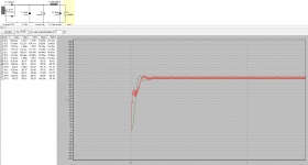
Running this quickly through PSUDII with a 40uF capacitor input filter (I'm limited to that because it's the max value for a 5U4GB and I want my rectifier to be switchable), I get the results in the attached picture. I'll drop the screen voltage a little lower to get a little bit of sag, since I want this to be a very touch-responsive clean amp.
The current tap of 113mA comes from twice the 56.5mA quiescent current in my 6L6GC load line. From all of my preamp tubes (and I have a few extra for driving a reverb tank/recovery/effects loop/cathode follower), I have around another 37mA. The 9.45kOhm load is the screen voltage, 350 volts, divided by 37mA.
The result I get from PSUDII looks promising, at least in the steady state - near-correct RMS plate voltage, near-correct screen voltage. If I'm on the wrong track here, though, I'm open to hearing about it. Please set me right - after all, I'm still a beginner.
The datasheet quotes a no load voltage of 654.3 volts. For a capacitor-input filter with a solid state rectifier, the expected no-load DC voltage should be 654.3/sqrt(2) = 462.6 volts.
Primary winding resistance is 2.619 ohms. Secondary winding resistance is 102.9 ohms. The equivalent resistance seen looking into the secondary is 102.9 + 2.619 / (125/654.3)^2 = 174.7 ohms.
Running this quickly through PSUDII with a 40uF capacitor input filter (I'm limited to that because it's the max value for a 5U4GB and I want my rectifier to be switchable), I get the results in the attached picture. I'll drop the screen voltage a little lower to get a little bit of sag, since I want this to be a very touch-responsive clean amp.
The current tap of 113mA comes from twice the 56.5mA quiescent current in my 6L6GC load line. From all of my preamp tubes (and I have a few extra for driving a reverb tank/recovery/effects loop/cathode follower), I have around another 37mA. The 9.45kOhm load is the screen voltage, 350 volts, divided by 37mA.
The result I get from PSUDII looks promising, at least in the steady state - near-correct RMS plate voltage, near-correct screen voltage. If I'm on the wrong track here, though, I'm open to hearing about it. Please set me right - after all, I'm still a beginner.
Attachments
Don't forget to include Heater current reflected to the primary winding with it's associated voltage droop on the primary, thus affecting the secondary B+ winding voltages...
The transformer magnetizing current "should" be fairly low if you have a good PT... But that is only vector added and should not be significant..
Don't forget screen current... can be 4mA to 8mA typically at idle for 6L6....
The transformer magnetizing current "should" be fairly low if you have a good PT... But that is only vector added and should not be significant..
Don't forget screen current... can be 4mA to 8mA typically at idle for 6L6....
You're right, you caught me trying to fast-type a post. I forgot to mention that the screen current was included in the remaining 37mA.Don't forget to include Heater current reflected to the primary winding with it's associated voltage droop on the primary, thus affecting the secondary B+ winding voltages...
The transformer magnetizing current "should" be fairly low if you have a good PT... But that is only vector added and should not be significant..
Don't forget screen current... can be 4mA to 8mA typically at idle for 6L6....
As for heater current dropping the primary voltage, this is actually the first I've heard of it. Can you tell me more?
I'll redo my sim at peak current in a little bit to see what the sag will be like. What is a "normal" amount of sag for heavily overdriven signals?
I had the same question. I thought if you stayed within the current ratings of the transformer, there wouldn't be any extra factor to consider. The 5v winding is rated for 3A, so you're good there with your 5U4. There seems to be plenty of current for the 6.3v winding, 5A. And 173mA for the B+ is good. And if you don't draw the full current in the B+, doesn't that free up extra current available to other windings? I have several books but I know I read that in one of them, although I can't recall which one at the moment. Maybe I misinterpreted what the exact meaning was?
Last edited:
- Status
- Not open for further replies.
- Home
- Live Sound
- Instruments and Amps
- Beginner Load Line Question