Then you'll understand that the question is meaningless............I fully understand what I am asking.
Just do that re-run of your work but this time with a 25uS or so audioband risetime to fix the fundamental mistakes, then you'll understand.................
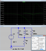
here's how minor a frequency response dip distorts group delay to > 10 microseconds
(no actual physical significance of RLC numbers expressed or implied)
do you have speakers that match peaks and dips of 1/3 dB R/L?
do dynamic drivers even hold frequency location of such minor diviots constant with drive level?
(no actual physical significance of RLC numbers expressed or implied)
do you have speakers that match peaks and dips of 1/3 dB R/L?
do dynamic drivers even hold frequency location of such minor diviots constant with drive level?
Attachments
Last edited:
Nope, you still fundamentally don't get it. There's a latency of 1.1uS for a 1uH cable and a 1 ohm load, when driven by an audioband risetime of 25uS. It has nothing to do with cable capacitance or rf characteristic impedance, depends only on cable inductance and load impedance. If the load is 8 ohms, latency is 0.13uS.
So let's see that re-run of your work but this time with a 25uS or so audioband risetime to fix the fundamental mistakes, when you do this you'll realise.................
You keep diverting away from what you did.
Run the sim using a real cable. Don't hide the fact that you've simulated using exactly what I recommended to solve the delay issue.
jn
Again, try simulation of a real cable. Don't try another strawman.Then you'll understand that the question is meaningless............
Just do that re-run of your work but this time with a 25uS or so audioband risetime to fix the fundamental mistakes, then you'll understand.................
jn
The first thing in my proposed audibility test includes both speakers powered mono. If the image is not stably centered, the test cannot move on.here's how minor a frequency response dip distorts group delay to > 10 microseconds
(no actual physical significance of RLC numbers expressed or implied)
do you have speakers that match peaks and dips of 1/3 dB R/L?
do dynamic drivers even hold frequency location of such minor diviots constant with drive level?
Are you proposing that since speakers are not that good, we don't have to even think about interchannel frequency based delays? Isn't the same true with distortion then, as speakers run percent numbers so can amps?
jn
Isn't the same true with distortion then, as speakers run percent numbers so can amps?
jn
You won't get a huge argument from me on that. You could also mix in LP's (another thread going on that now too).
Yes, group delay arising from real loads totally swamps any such effect being discussed here. The Bateman article linked earlier on this thread has a 2 driver + crossover spice speaker model, FWIW. Really, in context, altering cable effects is so lost in the swamp.here's how minor a frequency response dip distorts group delay to > 10 microseconds
(no actual physical significance of RLC numbers expressed or implied)
do you have speakers that match peaks and dips of 1/3 dB R/L?
do dynamic drivers even hold frequency location of such minor diviots constant with drive level?
You really have speakers with a 1R resistive load impedance ? Even then there's negligible delay in the audioband, and particularly negligible delay with 8R load.Don't hide the fact that you've simulated using exactly what I recommended to solve the delay issue.
There is no delay issue to solve, but it can't hurt to reasonably minimise inductance. If that's what you're suggesting in an obscure way, you're right even if for all the wrong reasons !
I love LP's. Problem is, the roads are so bad now that they don't play well in my car..You won't get a huge argument from me on that. You could also mix in LP's (another thread going on that now too).
jn
You really have speakers with a 1R resistive load impedance ? Even then there's negligible delay in the audioband, and particularly negligible delay with 8R load.
There is no delay issue to solve, but it can't hurt to reasonably minimise inductance. If that's what you're suggesting in an obscure way, you're right even if for all the wrong reasons !
You've chosen to model arbitrarily spectacular cables consistent with my recommendations, yet continue with your strawman arguments.
And yes, there are speakers that drop to 1 ohm. Not many.
When are you going to increase you model inductance to real zip cord? Trust me, we all know what the result will be...latency running about what, 5.5 uSec?
Geologic, eh?
jn
The Bateman article linked earlier on this thread has a 2 driver + crossover spice speaker model,
Oh, golly gee..someone forgot that there was also a picture showing the reflection signal from the mismatched load.
Holy mackeral, shouldn't reflections know better than to show up on a REAL speaker cable?? After all, what is the wavelength of 10Khz???? Isn't it like, a bazillion miles..😉
Enough of that.
My recommendations are based on a strong model of a cable using T-line. We all agree that T-line theory is far stronger that a simple LCR model, and is extremely accurate with respect to a 201 element LCR model.
It points out the real delay imposed by impedance mismatches at both ends of the line, and the relationship between the line z, length, and load z. You can hem and haw all you want, call it latency, or as I referred to following error (temporal error).
A realistic model using 201 LCR elements predicts the EXACT SAME delay as I've predicted using T-Line.
Both methods agree with actual measurements.
Your hangup seems to be your bandwidth limiting schtick.. You have to get a grasp of this ITD delay thing, as numbers as low as 2 to 5 uSec are REALLY inconsistent with the thinking of 20 Khz bandwidth. Unholy inconsistency as it were.
But reality nonetheless.
The takeaway with my recommendations is to indeed lower inductance, but I set a specific target to minimize the overall delay spread for typical (or atypical) speakers. Going too low in L raises C too much, I would be concerned with stability.
jn
Last edited:
Tough to say what that image shows, most likely simply current and voltage phase lag at 10kHz when the load is reactive - no surprises there. It can't arise from the cable, for all the reasons already set out, and there's a perfectly plausible explanation otherwise.Oh, golly gee..someone forgot that there was also a picture showing the reflection signal from the mismatched load.
Holy mackeral, shouldn't reflections know better than to show up on a REAL speaker cable?? After all, what is the wavelength of 10Khz???? Isn't it like, a bazillion miles..😉
A man sees what he wants to see and disregards the rest, as the song goes.
Tough to say what that image shows, most likely simply current and voltage phase lag at 10kHz when the load is reactive - no surprises there. It can't arise from the cable, for all the reasons already set out, and there's a perfectly plausible explanation otherwise.
A man sees what he wants to see and disregards the rest, as the song goes.
Um, your argument here is with HP. They are the ones who made the reflection bridge.
Are you now taking HP to task for their erroneous understandings???
You may stand a better chance downloading the HP manual and learning how their bridge works, that to explain to them that it shouldn't work because you said so.
jn
ps..quoting verse is probably not a good thing to do when you don't understand the subject...but that's just my opinion..
Last edited:
At 20kHz a one cell model will agree too.jneutron said:A realistic model using 201 LCR elements predicts the EXACT SAME delay as I've predicted using T-Line.
Both methods agree with actual measurements.
A 20kHz signal can be delayed by 5us and still remain band-limited, so in what sense is there any inconsistency?You have to get a grasp of this ITD delay thing, as numbers as low as 2 to 5 uSec are REALLY inconsistent with the thinking of 20 Khz bandwidth.
No, at audio bandwidth there's no worthwhile difference is what we all agree, including the likes of Davis and Greiner. You too, jn.We all agree that T-line theory is far stronger that a simple LCR model, and is extremely accurate with respect to a 201 element LCR model.
Yes totally. Specifically those tests, measurements and models which use or assume 'step' rise times faster than audio bandwidth permits. You overlooked it, that's your mistake along with misapplication of TL terms to circumstances where they have no meaning.jneutron said:Your hangup seems to be your bandwidth limiting schtick..
What IS inconsistent with 20kHz bandwidth is a 'step change' with 1nS rise time, the incorrect basis for your behaviour ideas and models.jneutron said:You have to get a grasp of this ITD delay thing, as numbers as low as 2 to 5 uSec are REALLY inconsistent with the thinking of 20 Khz bandwidth.
Now that IS a genuine rf issue involving amp, cable and load.jneutron said:Going too low in L raises C too much, I would be concerned with stability.
Please reread post # 592. I mentioned what the context is.You asked a question within the context of my statement (which you quoted)
Please reread post # 592. You can post what you want. I just wanted to know where you are coming from. So far, it looks like you aren't coming from known audible tweak product.Within the context of cable lifters or stands, are you again saying that unless I've performed DBT's with them, you have ruled that I cannot post?
Really?
You can start a new thread if you want to talk about speaker cable and its audible properties.
No, at audio bandwidth there's no worthwhile difference is what we all agree, including the likes of Davis and Greiner. You too, jn.
Not quite, nice try..
Yes, specifically tests, measurements and models which use or assume 'step' rise times faster than audio bandwidth permits. You overlooked it, that's your mistake along with misapplication of TL terms to circumstances where they have no meaning.
You still have not grasped the concept. At every frequency, a system cannot operate faster than it's high speed step response. You call it latency, I call it delay. You have even demonstrated that concept with your 25 uSec ramp, but you do not understand it.
As to stability:
Now that IS a genuine rf issue involving amp, cable and load.
No, you do not understand. It is not an RF issue. I recommend you look for some good reading material.
When a cable has a low impedance, the capacitance is very high (I provided the equational relationship earlier).
When the tweeter unloads above it's working frequencies, what remains is the cable storing energy via capacitance. An amplifier with feedback will lose it's margin when the output sees excessive capacitance.
That is when a zobel comes into play. It presents a low enough load at higher frequencies such that the amplifier doesn't see capacitive storage, so it's phase margin is preserved.
A very low impedance cable on a hot amp has to be zobel terminated so that the phase margin remains stable up to the amplifier's open loop unity gain point.
Basic circuit stuff.
jn
Please reread post # 592. I mentioned what the context is.
Your question was in post 612, so I responded within that context. The "look it's halleys comet" thing doesn't work here, and I can't read your mind.
I just wanted to know where you are coming from.
Then why say something stupid? Just ask me where I'm coming from.
No big thing..
You can start a new thread if you want to talk about speaker cable and its audible properties.
As opposed to a discussion about speaker cables and it's audible properties when propped?
Ah, the thread content police.
And honestly, I arrived at this party after what, 300 posts or so talking about cable impedance and t-line.
Don't you think you should have policed the thread about 5 weeks ago?
Oh, forgot to mention. Why is it you're posting ridiculous statement about me talking about cables, when there are about 5 people engaged in this discussion. You should be yelling at everybody. Is it because you love me??😉
jn
Last edited:
That's a same question asked second time.Your question was in post 612
Despite asking you multiple times, you still have nothing to offer as far as audible aspect of speaker cable lifters on this audio forum.Then why say something stupid? Just ask me where I'm coming from.
No big thing..
As opposed to a discussion about speaker cables and it's audible properties when propped?
Ah, the thread content police.
And honestly, I arrived at this party after what, 300 posts or so talking about cable impedance and t-line.
Don't you think you should have policed the thread about 5 weeks ago?
Oh, forgot to mention. Why is it you're posting ridiculous statement about me talking about cables, when there are about 5 people engaged in this discussion. You should be yelling at everybody. Is it because you love me??😉
jn
One thing you did get from filling up the forum bandwidth is the attention that you crave. 🙄
Firstly the HP 8721A bridge is a 50R rf tool rated for frequencies 100kHz - 110Mhz, ie not intended or rated for the audio band. Secondly, it has a 50R series passthrough resistance between source and load so significantly alters measurement conditions when placed in series with speaker cables and loads. Thirdly, its internal schematic is very simple and can be simulated in the context you suggest at 10kHz, along with the simulated speaker load used.Um, your argument here is with HP. They are the ones who made the reflection bridge.
Are you now taking HP to task for their erroneous understandings???
You may stand a better chance downloading the HP manual and learning how their bridge works, that to explain to them that it shouldn't work because you said so.
Doing this did not require any speaker cable at all to obtain phase shifts at 10kHz consistent with your claims, jn. In other words it appears to be plausible as simply an artefact of the measurement method, no surprises there.
You can't defy the laws of physics captain.
Last edited:
- Status
- Not open for further replies.
- Home
- Member Areas
- The Lounge
- Speaker Cable lifters or stands?