Hey Anyone,
I think I understand LED biasing but rather than ask a million questions maybe someone could tell me if and how I'm wrong? Lets say you are working with a yellow LED that has a forward voltage of 1.2 volts. A minimum current of 5 ma and a maximum of 20ma. I think the forward voltage corresponds to the grid line on the load line graph for a tube? If that's correct then you would draw a vertical line at your B+ and where that line intersects the load line is the bias point. Now draw a horizontal line intersecting that point and then read the current from that line.
I've attached an example, (6GK5) where the voltage is -1.2. the B+ is 136 and the current 9 ma.
Thanks, Kevin
Attachments
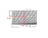
I think you draw your load line normal, so say 10k, B+ is 136, 136/10000=.0136 Now find where -1.2 crosses that load line, looks like 3mA.
Yes, this is correct, except for the error in LED voltage.
You select the LED based on the required bias point, which is it's forward voltage drop. Different colors (or IR) for different bias voltages. Draw the loadline depending on the anode load as usual. Next, draw the horizontal line from the bias point/FVD on the loadline to the plate current axis et voila, you have the quiescent current passing through the LED.
LED's do have non-linearities unfortunately. The datasheet shows you what current region is most linear. If your in luck, the given tube's operating point will give the necessary current. If not, you can supply the extra needed current with a resistor parallel to the tube (B+ to cathode). A typical red LED used in a 12ax7 stage for example (+/- 2mA) will benefit from the extra current.
LED's do have non-linearities unfortunately. The datasheet shows you what current region is most linear. If your in luck, the given tube's operating point will give the necessary current. If not, you can supply the extra needed current with a resistor parallel to the tube (B+ to cathode). A typical red LED used in a 12ax7 stage for example (+/- 2mA) will benefit from the extra current.
Last edited:
Yes, this is correct, except for the error in LED voltage.
Yes true, 1.2 is a red LED.
Yes true, 1.2 is a red LED.
No a Red Led is typically 1.7v
Forward voltage of all LED types is provided here:
Light-emitting diode - Wikipedia, the free encyclopedia
Take what ever the B+ and plate load you are using and draw the load line. Since you are dealing with what is effectively a voltage reference to bias with, find that voltage on the load line and see if the resulting current is within the LED limits.
All red LED's are not created equal. There are several variants. The better( more ideal voltage ref's) ones *DO* develop ~1.2V across them when lit properly.
cheers,
Douglas
in the original example, I think the term B+ is improperly used; the more likely intent being 'plate voltage'.
All red LED's are not created equal. There are several variants. The better( more ideal voltage ref's) ones *DO* develop ~1.2V across them when lit properly.
cheers,
Douglas
in the original example, I think the term B+ is improperly used; the more likely intent being 'plate voltage'.
If your in luck, the given tube's operating point will give the necessary current. If not, you can supply the extra needed current with a resistor parallel to the tube (B+ to cathode).
The extra LED current can also come from a separate low voltage supply.
In fact, this is much more practical, since the HV supply won't usually be able to supply this level of extra current.
Take what ever the B+ and plate load you are using and draw the load line. Since you are dealing with what is effectively a voltage reference to bias with, find that voltage on the load line and see if the resulting current is within the LED limits.
All red LED's are not created equal. There are several variants. The better( more ideal voltage ref's) ones *DO* develop ~1.2V across them when lit properly.
cheers,
Douglas
in the original example, I think the term B+ is improperly used; the more likely intent being 'plate voltage'.
Can you provide a data sheet where such a 1.2v Red Led is available please,
Here is one from Vishay where 1.8v to 2.2v is the rated forward voltage @20ma
http://www.vishay.com/docs/83004/tldr5800.pdf
No a Red Led is typically 1.7v
Forward voltage of all LED types is provided here:
Light-emitting diode - Wikipedia, the free encyclopedia
Wikipedia

Typical yes. BUT from memory I remember working with some really low current red leds that would develop 1.2v with a 12AX7, datasheet said 1.5v
Sorry I can't provide you with hard evidence at the moment.
Wikipedia
Typical yes. BUT from memory I remember working with some really low current red leds that would develop 1.2v with a 12AX7, datasheet said 1.5v
Sorry I can't provide you with hard evidence at the moment.
I have managed to find a 1977 Hewlett Packard Opto Devices catalog
and indeed forward voltage was lower on a number of available LED products
for instance the 5082 series could achieve 1.6v at 5ma according to the
available graphs:
http://ftp.df.lth.se/pub/bitsavers.org/pdf/hp/_dataBooks/1977_Optoelectronics_Designers_Catalog.pdf
My memory of first seeing LED's was on a Quad 405 and they used
the 5082 - 4850
Last edited:
1.2V drop would be more typical of an infrared LED. The deepest red LEDs on the market (the original GaAsP types) chime in at~1.6V at 10ma of bias current.
Measure your LED's forward drop before you use them. Then measure the forward drop as they get warm in your circuit.
You will likely find that it is userful to match LED's and that the forward volts decline as they get warmer.
Tubes are very robust and can operate at a very wide range of voltages, but for nice channel-to-channel matching, I find it important to match the bias points as closely as possible, using the bias point when an LED is warm.
Maybe I'm too picky.
Ian

You don't need to feed extra current to the LED. It only increases the bias voltage a bit, which increases rather than reduces distortion.
The extra LED current can also come from a separate low voltage supply.
In fact, this is much more practical, since the HV supply won't usually be able to supply this level of extra current.
How is it more practical to route the leads from a separate supply, instead of just using one resistor from B+ to the cathode??. That is assuming there even is a DC voltage (heaters maybe) at hand.
Any proper PSU should have no problem providing the extra few mA's.
You don't need to feed extra current to the LED. It only increases the bias voltage a bit, which increases rather than reduces distortion.
Are you referring to yellow in particular or in any situation?
Any situation where a single LED is used for bias.Are you referring to yellow in particular or in any situation?
Why would increasing the LED current increase distortion? Doesn't it reduce the LED dynamic impedance and so reduce distortion?
The LED dynamic resistance non-linearity is negligible compared to the internal cathode impedance non-linearity. Any improvement in LED resistance is more than offset by the increase in bias voltage that comes from running the LED at higher current, so you get more valve distortion. (Not much more, I grant you)Why would increasing the LED current increase distortion? Doesn't it reduce the LED dynamic impedance and so reduce distortion?
OK, I assumed people would only add extra LED current in order to bring the valve bias up to the correct point, not to go away from the correct point.
So, if the outcome is a correctly-biased valve then increasing LED current will reduce valve distortion just as expected. It will also reduce the (already quite small) LED distortion.
So, if the outcome is a correctly-biased valve then increasing LED current will reduce valve distortion just as expected. It will also reduce the (already quite small) LED distortion.
- Status
- Not open for further replies.
- Home
- Amplifiers
- Tubes / Valves
- LED Biasing