Hi all,
Planning to build LM3875 amp with pcb from Chipamp..
Non-Inverting LM3875 Stereo Kit | Chipamp Electronics
To drive small "monitor" speakers (6 Ohm), I dont need much power, maybe 5/10 watts.
First time building LM3875, I will use toroid 80Va 12 vac, and snubberized PSU :
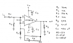
Amp schematic :
About Cs (1500 uF), not sure it's the good value for my use ?
The goal is to have a very smooth response (500 to 4000 hz), sounstage is not a problem, just tone amp.
Your advice ?
Phil.
Planning to build LM3875 amp with pcb from Chipamp..
Non-Inverting LM3875 Stereo Kit | Chipamp Electronics
To drive small "monitor" speakers (6 Ohm), I dont need much power, maybe 5/10 watts.
First time building LM3875, I will use toroid 80Va 12 vac, and snubberized PSU :
An externally hosted image should be here but it was not working when we last tested it.
Amp schematic :
An externally hosted image should be here but it was not working when we last tested it.
About Cs (1500 uF), not sure it's the good value for my use ?
The goal is to have a very smooth response (500 to 4000 hz), sounstage is not a problem, just tone amp.
Your advice ?
Phil.
Last edited:
Only 5 to 10 watts? I'd use the LM1875. With 12.6-0-12.6 2A transformer you'd get around 12 watts of unclipped power both channels driven continuous into 6 ohms.
Either way, use single bridge rectifier. Why incur four diode drops?
Decouple IC with film caps near to the IC. If main filter caps are more than 10cm from the IC use ~330uf 'lytics near the IC. Audio doesn't need DC coupling. Use caps as shown on datasheet or risk other complications.
Add RF lowpass on input and don't forget proper ground layout.
.
I have to agree with johnr66. The LM1875 seems much better suited to your requirements.
At the same time I wonder. Is there some specific design goal that calls for the changes you made to the "Typical Application" circuit in the data sheet?
The chip and the circuit it works in are designed side-by-side by a team at least one senior, and several junior, engineers. They work in a lab equipped with tens of thousands of dollars worth of test equipment. The chip they finally design will be manufactured in the millions, there's no room for error.
All of which is boiled down for we DIYers into the "Typical Applications" circuit. A simple little thing with hundreds of thousands of dollars in research and development costs behind it.
If you just want to fool with a chip, do this or that and see what happens, well then I say go ahead and power to you. That's what these forums are for.
But if you just want to get the job done and go on to something else, then I can see no reason to change what the factory--which created the chip in the first place--recommends. Doing so is just throwing away a very large amount of engineering expertise, which seems pointless unless it's required by some specific design goal.
.
Last edited:
Hi Mark,
I had thought P2P, but I need a huge magnifying glass 🙂
Hi John,
Why LM3875 and this psu, cause I have.
I will add a safety loop breaker and a "proper" ground.
"If main filter caps are more than 10cm from the IC use ~330uf 'lytics near the IC"
I keep your advice.
Thank's.
Phil.
I had thought P2P, but I need a huge magnifying glass 🙂
Hi John,
Why LM3875 and this psu, cause I have.
I will add a safety loop breaker and a "proper" ground.
"If main filter caps are more than 10cm from the IC use ~330uf 'lytics near the IC"
I keep your advice.
Thank's.
Phil.
Hi,
Maybe you are right, but I build several LM3886, with "Typical Application" and other by changing some value or quality componant, I prefer "tweaking".
My previous amp :
http://www.diyaudio.com/forums/chip-amps/265827-lm3886-fullrange-9.html#post4261577
Everything is changed regarding typical schematic, and it's sound better (for my taste)..
And this has been possible with the help received here !
Phil.
.
At the same time I wonder. Is there some specific design goal that calls for the changes you made to the "Typical Application" circuit in the data sheet?
.
Maybe you are right, but I build several LM3886, with "Typical Application" and other by changing some value or quality componant, I prefer "tweaking".
My previous amp :
http://www.diyaudio.com/forums/chip-amps/265827-lm3886-fullrange-9.html#post4261577
Everything is changed regarding typical schematic, and it's sound better (for my taste)..
And this has been possible with the help received here !
Phil.
DC coupled.Hi all,
Planning to build LM3875 amp with pcb from Chipamp..
Non-Inverting LM3875 Stereo Kit | Chipamp Electronics
To drive small "monitor" speakers (6 Ohm), I dont need much power, maybe 5/10 watts.
First time building LM3875, I will use toroid 80Va 12 vac, and snubberized PSU :
An externally hosted image should be here but it was not working when we last tested it.
Amp schematic :
An externally hosted image should be here but it was not working when we last tested it.
About Cs (1500 uF), not sure it's the good value for my use ?
The goal is to have a very smooth response (500 to 4000 hz), sounstage is not a problem, just tone amp.
Your advice ?
Phil.
Do you intend installing output offset detection?
Do you intend installing load protection?
No RF attenuation.
No HF supply rail decoupling.
No output inductor with damping resistor.
You have shown Cz connected to the NFB connection and to the Signal Hot connections. These two should actually be connected to the Signal Return circuit, but you have omitted that.
Last edited:
I prefer "tweaking"
Works for me. Like I said before, fire another broadside and no prisoners. Or I might not have said exactly that, but I would have if I'd thought of it at the time.
.
If you want better stability near clipping, I suggest adding Cc, Rf2, and Cf as shown in attached schematic.
If you'd like your amp to be able to drive capacitive loads (long speaker cables, for example), I also suggest adding a Thiele network (L || R) in series with the output. I use L = 2 uH; R = 1.5 ohm. 15 turns of AWG 18 (1.0 mm diameter), 20 mm long wound on an AA battery is about 2 uH.
I suggest putting the snubber across the transformer secondary. That's where the diode switching transients occur. 100 nF across the secondary will reduce the frequency of the ringing to the point where it doesn't couple anywhere. You can optimize a snubber there if you feel like it, but in my experience, it makes no difference on the supply output (or amp output for that matter). This is the subject of great debate, so others may disagree...
With a 12 VAC transformer, you'll end up with about +/-16 V on the reservoir caps. That works well for a low-power LM3875, LM3876, or LM3886.
~Tom
Attachments
Last edited:
Hi all,
At first I would build a minimized GC, but I realize that it can work perfectly !
I add Cc 220 pF (I have not 180 pF), but it's very close.
About Cf and Rf2 like Tom advises, I will try without and with, to hear the difference ?
At beginning, I build amp on wood board, like this :
So, it's easy to change something..
I agree, low-power with LM3886 works well, I have one working with 17/0/17 volts..
Cable are 1,5 m lenght, so Thiele network is not needed.. On the pict above I have.
Tom, you advise add a cap 100 nF across secondary, I thought polypro quality ?
Pcb from Chipamp are the same as Audiosector :
Phil
At first I would build a minimized GC, but I realize that it can work perfectly !
I add Cc 220 pF (I have not 180 pF), but it's very close.
About Cf and Rf2 like Tom advises, I will try without and with, to hear the difference ?
At beginning, I build amp on wood board, like this :
An externally hosted image should be here but it was not working when we last tested it.
So, it's easy to change something..
I agree, low-power with LM3886 works well, I have one working with 17/0/17 volts..
Cable are 1,5 m lenght, so Thiele network is not needed.. On the pict above I have.
Tom, you advise add a cap 100 nF across secondary, I thought polypro quality ?
Pcb from Chipamp are the same as Audiosector :
An externally hosted image should be here but it was not working when we last tested it.
Phil
>> Tom, you advise add a cap 100 nF across secondary, I thought polypro quality ?
Maybe X2 was better ?
Phil.
Maybe X2 was better ?
Phil.
Any film cap will do.
Cc = 220 pF is fine. It is there to ensure amplifier stability near clipping. The drawback of Cc is that it creates a zero in the loop response which causes overshoot on the transient response. To tame this overshoot and clean up the transient response, Rf2 and Cf are added.
~Tom
Cc = 220 pF is fine. It is there to ensure amplifier stability near clipping. The drawback of Cc is that it creates a zero in the loop response which causes overshoot on the transient response. To tame this overshoot and clean up the transient response, Rf2 and Cf are added.
~Tom
Tom,Any film cap will do.
Cc = 220 pF is fine. It is there to ensure amplifier stability near clipping. The drawback of Cc is that it creates a zero in the loop response which causes overshoot on the transient response. To tame this overshoot and clean up the transient response, Rf2 and Cf are added.
~Tom
can you describe a "tuning" procedure to find the values of Rf2 & Cf to match the zero introduced by the Cc?
In a discrete amp I used Cf alone (Rf2=0) to attenuate the overshoot.
But this value depended on what was applied to the output.
It needed different Cf, so I settled on one value that seemed to give acceptable overshoot on most output loadings.
I was not satisfied with this, so I ask now how to do it better.
Tom,
can you describe a "tuning" procedure to find the values of Rf2 & Cf to match the zero introduced by the Cc?
Very interesting question..
With 47 pF (or close to), I find only ceramic cap, other quality advice for Cf ?
Phil.
Hi,
First listening, well done !!
Amazing how this "little amp" can works..
Some mesurements, psu give 17,5 volts, DC offset 5 and 7 mV at normal level ( near 6 Ohm load, pot is 10 K near 10 AM ), with ridiculous heatsink you can see temp is 32° (22° inroom)..
I need more hours of listening, but at first, I can tell : very smooth and "huge" dynamic mid/high.
Phil.
PS : with LM's, I still observe that it's works better with" low power" 🙂
An externally hosted image should be here but it was not working when we last tested it.
An externally hosted image should be here but it was not working when we last tested it.
First listening, well done !!
Amazing how this "little amp" can works..
Some mesurements, psu give 17,5 volts, DC offset 5 and 7 mV at normal level ( near 6 Ohm load, pot is 10 K near 10 AM ), with ridiculous heatsink you can see temp is 32° (22° inroom)..
I need more hours of listening, but at first, I can tell : very smooth and "huge" dynamic mid/high.
Phil.
PS : with LM's, I still observe that it's works better with" low power" 🙂
Hi,
Just received all parts for to continue..
I bought Hifi2000 case, and I saw several M86 builder using same case and fix LM at side of case, like this :
Maybe "A" is enough, but "B" seams bad way..
Material is very thin, 1,5 mm behind LM.
I think add alu bare 4 mm thinkness, like this :
That give 5,5 mm (and 120 mm lenght), bare was attach with thermal past and side case painting will be removed..
Some experiment with that setup ?
At first time, I wanted to use copper, but I don't find with cheaper price..
Phil.
Just received all parts for to continue..
I bought Hifi2000 case, and I saw several M86 builder using same case and fix LM at side of case, like this :
An externally hosted image should be here but it was not working when we last tested it.
Maybe "A" is enough, but "B" seams bad way..
Material is very thin, 1,5 mm behind LM.
I think add alu bare 4 mm thinkness, like this :
An externally hosted image should be here but it was not working when we last tested it.
That give 5,5 mm (and 120 mm lenght), bare was attach with thermal past and side case painting will be removed..
Some experiment with that setup ?
At first time, I wanted to use copper, but I don't find with cheaper price..
Phil.
why not just scavange an old CPU cooler?
I bet You can find one.
then all it takes to amke it work is to drill a single hole on it.
it will be a far better solution vs this heatsink.
the middle alu thingy on pic C does not seem to be a wise idea.
heat transfer between the chip and its heatspredder, the to the alu thingy, and then to the heatsink... too many steps.
if nothing else, then find a dead pc powersupply.
those have suitable heatsinks as well.
inferior to a cpu heatsink, but still miles better than that thing.
Tom,
can you describe a "tuning" procedure to find the values of Rf2 & Cf to match the zero introduced by the Cc?
In a discrete amp I used Cf alone (Rf2=0) to attenuate the overshoot.
But this value depended on what was applied to the output.
I recommend running a standard loop gain sim. I use a giant LC filter to "break" the loop and plot the loop gain. You can see this technique in action in the Stability section of my Taming the LM3886 page.
Add Cc and watch the phase margin go to heck. Then add Cf and place the zero slightly above the unity gain frequency. You'll now notice that the PM may be decent, but the gain margin will only be a few dB (need >10 dB, preferably). Add Rf2 to introduce a pole in the feedback loop. Now you have both good PM and GM, as well as the improved clipping performance introduced by Cc.
In the lab, the effect of Cc is easy to spot. Just run a sine wave into the amp and load the amp with an 8 Ω resistor. Crank up the volume until the amps just starts to clip. About 1 V before the output hits the rails, you'll notice that the LM3886/LM3875/LM3876 shows some quasi-oscillation near the top part of the sine wave. Add Cc until the quasi-oscillations go away.
Now switch the source to provide a 10 kHz square wave. Adjust the amplitude until you get a, say, 10 Vpp amplitude on the amp output. You'll notice that the transient response has a bit of overshoot. Add Rf2 and Cf to remove the overshoot. I suppose you could tweak the values in the lab, but unless you have a network analyzer and the capability to measure the loop gain and phase, I suggest optimizing the network in the simulator and just verifying the transient response in the lab.
~Tom
Very interesting question..
With 47 pF (or close to), I find only ceramic cap, other quality advice for Cf ?
Phil.
47 pF NP0/C0G ceramic will be fine here.
~Tom
- Status
- Not open for further replies.
- Home
- Amplifiers
- Chip Amps
- LM3875 Chipamp