My problem with the last thread was that this was not proven with any engineering rigor. We did this in 1991 on a datasheet with an AD1862 DAC, the RFI suppression was measured with a broadband spectrum analyzer and it was considerable. As people have mentioned op-amps especially vintage ones like 5532's have an inductive output impedance at high frequencies and using the integrating filter capacitor across the I/V resistor fails at high frequency.
No experiment has been proposed so far that eliminates this and isolates the simple BW limiting, though I have to admit I've lost track of exactly what is being claimed.
Scott,
I don't think that ayone is denying any of what you recount. What I find intriguing about the effect is that it seems to perceptually 'activate' with only a seemingly trivial lowering in turnover frequency of an simple 1st order output filter.
The current suspicion is that the percieved effect is likely not due to frequency doman filtering, as the ultrasonic and RF supression masking difference simply seems too trivial. This has led to the conjecture that the effect is instead primarily due to changes in DAC output node time domain behavior. However, perhaps this conjecture is itself wrong, and the effect is in fact due only to the very slight improvement in frequency domain filtering as some suggest. Yet another possibility is that it's simply some psychoacoustical effect due to the now in-band upper edge response roll-off, however, the sound character change /improvement is quite obvious, subjectively manifesting across the entire audio band.
The cause would be much easier to isolate if some of us had access to a lab and a sacrificial DAC to hack around on, instead of working in our basements and needing our DACs to enjoy listening as well. 🙂
Thanks for suggestions. Some of it are quite difficult to follow, but I will try to find ways to get more infos out of this approach...
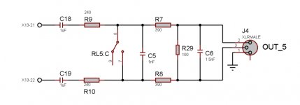
In the mean while if it may be convenient for you, maybe you will try to solder these two caps into your device, to observe what happen.
Coris, the DAC I’m using for more than 2 years has no I/V stage (DAC chip with voltage outputs). Yet its analog filter is similar to proposed configuration since it has a cap across + and - outputs (pretty common configuration). Difference is in higher R and lower C values than proposed in previous thread (the values proposed there would be IMO unreasonable challenge to the driving capability of analog outputs).
I came to this values after little experimenting, the FR is mildly rolled to -0.8dB @20kHz. I’m quite satisfied with its performance including the sound-stage it throws. I would restrain from further experimenting as the board is already burdened with certain changes and I’m afraid further modifications may lead to failure.
In regard to this effect, my guess is you have encountered some specific psychoacoustic effect triggered by amplitude and especially phase modification introduced by a simple single-pole low pass filter with fc ~ 27kHz, possibly in combination with the phase characteristics of digital reconstruction filters of contemporary DACs. Perhaps time will tell.
As I`ve wrote previously, I suspect something here it have impact in phase area of the signals. And what it may happen is of a positive sort for human hearing/perception, or it improve the sonic environment for a stereo configuration.
As also as I`ve wrote previously, I decided to start again this thread, mainly because I could find the same effect when applying this filtering, or these capacities over the differential lines at the inputs of an pre-amplifier device/stage.
I see the discussion is further focused around the use of such cap at the DAC outputs, and one try to explain the effect by changes in the HF/LF interactions at a such device outputs.
In my opinion, and as I have experienced, this effect it is revealed too when to place this cap (on differential lines) other places than only at an DAC outputs.
So, it may be even easier for someone to try it this at an preamp device inputs.
You are describing something different to Mr. Rasmussen zobel. He suggests a filter after the opamp or using a software filter to return the signal to its original state.
That is what a filter does.Coris said:As I`ve wrote previously, I suspect something here it have impact in phase area of the signals.
A cap placed across differential lines will provide:Coris said:In my opinion, and as I have experienced, this effect it is revealed too when to place this cap (on differential lines) other places than only at an DAC outputs.
So, it may be even easier for someone to try it this at an preamp device inputs.
1. differential mode filtering, probably low pass, when combined with whatever was already there;
2. common mode noise/interference/buzz injection via its stray capacitance to whatever electric field sources are nearby.
Both effects could be audible, under the right circumstances.
And a website to collect royalties.
Improving Digital Audio – A New Digital to Analog Conversion Post-DAC Solution:
Improving Digital Audio – A New Digital to Analog Conversion Post-DAC Solution:
Since I did this a decade ago, can I please claim this as 'the Didden cap'? 😉
Hey, I even had an article published about it! Never realised I was sitting on gold....!
@ SY: stop feeding it!!
Jan
Man, this thread is not about who was first, who did invented this, or who`s name the approach should take.
How do you suggest to call this cap placed so how it is? Filtering cap? There are so many filtering ways. How to differentiate this circuit from others?
Shall we call it Jan & Joe`s cap? Or J&J`s cap?
Is this so important? There is actually the circuit itself which is in discussion here, but not who used it first.
Actually I personally could not read here in this forum about your article. But it was Joe who presented this way to place the cap, as a filter, to improve the sound out of an Oppo player. It was quite a particular case to use what some other peoples used before in their own design or designs of consumer products. I saw my self that such a cap it was used in many other circumstances. But it was Joe who (read it about somewhere, or found it out himself) came in Oppo thread with this idea. I was then the first who applied it right on a Oppo player, and I could confirm in the same thread about the improvements. Then it was Ken Newton who was for sure embarrassed to use so many words to refer to this approach, so called it him "Rasmunssen effect", to have a name to use it in discussions. And this name it was enough to put on fire lot of people, turn the technical discussion into many personal attacks, and so on.
Can we never go out of this blind alley?
I will kindly suggest to turn us to the technical things...
I think it may be beneficial for all of us (maybe some had not yet the pleasure to read your article), to come here with some extracts from it, and from your findings that time, as a contribution to a better understanding of why we get improvements when using this cap.
Last edited:
That is what a filter does.
A cap placed across differential lines will provide:
1. differential mode filtering, probably low pass, when combined with whatever was already there;
2. common mode noise/interference/buzz injection via its stray capacitance to whatever electric field sources are nearby.
Both effects could be audible, under the right circumstances.
There is very well then. We have an answer.
Shall we close the discussion/thread, or shall we wait for the moderators to do it?😀
You are describing something different to Mr. Rasmussen zobel. He suggests a filter after the opamp or using a software filter to return the signal to its original state.
From my part, I may agree that I`ve try it first the simplest way, with just a cap, to observe what it may be the impact of a simple cap on the DAC chip outputs. It worked just fine, and I could confirm the improvements. I think Joe it complicated a little bit the approach. Well, may be better to complete the filter so with R components, etc.
But it worked for me so, the simplest way. For sure this cap interact with the existent circuits both R and H.
Then I thought to use this simple cap in another place than only on DAC outputs, just to try what it may happen (well, I had my logic in doing so). It worked again, as described previously.
I myself open to a better way to do it. It may be even more improvements when composing this filter in a more scientific way. As I can see so far, there is enough scepticism about using such approach, no mater in its simple version or in a the more complicated one. At least the simplest way is much more easy to implement it.
I would like to use the opportunity to make an general observation about this discussion here. This and many other threads here are read it (only) by lot of peoples who never say something, nor even good or bad. But those silent part of the forum users, goes through the posts, grab the ideas, experiment and put in practice what it come out from the discussions here. In other words they use the informations, and succeed in their attempts. Sometimes, one or another of these silent members, come out with confirmations.
Here is an example from the Oppo 95 thread:
"- capacitor between DAC output stages (love it!!!! 0.01uF)" from Qkizz , one of his posts.
Last edited:
Man, this thread is not about who was first, who did invented this, or who`s name the approach should take
Of course it is, Joe and you made it that way to attach names to a simple filter cap and setting up a paypal account to collect royalties on a filter cap!
I think you missed the sarcasm in my post.
Jan
I think it may be beneficial for all of us (maybe some had not yet the pleasure to read your article.
As others have made clear, what apparently has been missed, it is NOT 'my' cap, it is nobodies cap, it is a simple well known measure to place a cap that way for filtering purposes, used much longer than your and my age.
The fact that you guys do not know these simple basic things apparently led you to think this is an 'invention'. Modesty is another virtue lost in this post-fact society. Humorous if it wasn't so sad.
Jan
If it is a linear filtering effect, then you can filter some music digitally to reproduce the expected effect and ABX it versus the original. That would be the first thing to try.
Member
Joined 2009
Paid Member
And a website to collect royalties.
Improving Digital Audio – A New Digital to Analog Conversion Post-DAC Solution:
At least it is a real component doing something. There's another thread around here, also closed I think, about a guy selling varnish - you paint it on a plank of wood, mount your amplifier pcb on this plank and the sound is magically transformed

It's going to be very messy doing an "ears only, simple listening test" - setting up A and B versions opens up another Pandora's box, in terms of precisely how does one do this without yet further physical complications to the setup - the one essential aspect is that it won't ... be ... simple!
Unfortunately, it is a bit of a nightmare world trying to nail these behaviour patterns - once one has established very straightforward sets of test signals, typically music tracks, to verify whether "something is happening or not", then the real focus of one's energy is on working out a solid solution - this is the real drama of the situation.
Unfortunately, it is a bit of a nightmare world trying to nail these behaviour patterns - once one has established very straightforward sets of test signals, typically music tracks, to verify whether "something is happening or not", then the real focus of one's energy is on working out a solid solution - this is the real drama of the situation.
.........made it that way to attach names to a simple filter cap and setting up a paypal account to collect royalties on a filter cap!
......................
Jan
😱😕 Fanny imagination...😀
Last edited:
If it is a linear filtering effect, then you can filter some music digitally to reproduce the expected effect and ABX it versus the original. That would be the first thing to try.
What about the first thing, to try to solder these caps, and then describe what you may hear?
At least this was the one and only (my) purpose in this thread as in the other ones:
To share the information about when using this cap in some precise places it leads to improvements. And such information it was meant for the ones who did not have it yet.
From my part, I may agree that I`ve try it first the simplest way, with just a cap, to observe what it may be the impact of a simple cap on the DAC chip outputs. It worked just fine, and I could confirm the improvements. I think Joe it complicated a little bit the approach. Well, may be better to complete the filter so with R components, etc.
But it worked for me so, the simplest way. For sure this cap interact with the existent circuits both R and H.
Then I thought to use this simple cap in another place than only on DAC outputs, just to try what it may happen (well, I had my logic in doing so). It worked again, as described previously.
I myself open to a better way to do it. It may be even more improvements when composing this filter in a more scientific way. As I can see so far, there is enough scepticism about using such approach, no mater in its simple version or in a the more complicated one. At least the simplest way is much more easy to implement it.
I would like to use the opportunity to make an general observation about this discussion here. This and many other threads here are read it (only) by lot of peoples who never say something, nor even good or bad. But those silent part of the forum users, goes through the posts, grab the ideas, experiment and put in practice what it come out from the discussions here. In other words they use the informations, and succeed in their attempts. Sometimes, one or another of these silent members, come out with confirmations.
Here is an example from the Oppo 95 thread:
"- capacitor between DAC output stages (love it!!!! 0.01uF)" from Qkizz , one of his posts.
Improving Digital Audio – A New Digital to Analog Conversion Post-DAC Solution:
Mr. Rasmussen discribes improvements with the filter placed directly after the dac chip only and that the interaction with the dac's internal circuit is the Rasmussen effect. If placing a similar filter after the op amp also works then you are disproving the Rasmussen effect.
We will need a new name for this second new circuit improvement. "CORIS EFFECT"
At least it is a real component doing something. There's another thread around here, also closed I think, about a guy selling varnish - you paint it on a plank of wood, mount your amplifier pcb on this plank and the sound is magically transformed
Where is the patent? How can you claim royalties without a patent!
At least selling varnish is selling something.
I`m not responsible for another peoples enterprises and actions. Actually I did not knew about this site, as I`m not obsessed by this subject so to investigate any new created website, looking for exactly this approach. But someone else it seems to have only this in mind...
At least Joe`s idea with creating this site it was good enough, to discuss so this subject in a closed forum (except the business aspect out of such...). What is happen here it confirm the benefit of such idea.
Anyway thanks for your advertising for this site. I will take a look...
I feel the need to repeat, that the main propose with this thread and another where I participate, is to share/exchange informations and impressions about something or another. At least the factual meaning of a open forum.
It looks to me that such positive personal imitative to share/exchange informations, is not appreciated by some ones. It may contradict with their interests, it may be disturbing, or something else? I do not know.
Sharing some personal findings and experiences (for free), thinking so it may be useful for another ones, it may be something positive in my opinion. However, as I can see here, I may be wrong in this way of thinking...
They who will want and appreciate these informations here it will use it, and maybe appreciated. The "rest" is free to do what they want, and go further with their rhetoric.
However, the idea to share informations for free, it may be wrong indeed, as someone else can use what they get for free to make money/business... I suppose I will have to reconsider something about this...
Last edited:
- Status
- Not open for further replies.
- Home
- Member Areas
- The Lounge
- The Joe`s capacitor...