EDIT: And after what has been a long, long time, and at least three revisions, PCB are now available here - WHAMMY Headphone Amplifier – diyAudio Store
Well illustrated build guide here - "WHAMMY" Pass DIY headphone amp guide
Just to create some interesting discussion, here is a preview of the new PassDIY headphone amp. Wayne's been working on this, and everything so far has been very, very promising.
A few answers first --
As of this post in March '15, it's not yet available. Hopefully it will be for sale in the diyAudio store before summer.
These photos are of the first, non-conforming PCB. The final version will look very similar, the changes for the revision are all very minor, mostly silkscreen stuff.
Of course, it's Class-A. The output stage is really neat.
It has no 'Klunk.' 😛😛😛
It will be able to drive any headphone to deafening levels. Gain can also be turned down for super-sensitive headphones.
The whole circuit is on the one PCB. Input jacks, output jacks, and AC are all chassis mount. Of course, you could chassis mount the pot as well. Or use a fancy stepped attenuator. This is DIY, after all. 😀

A photo of a partially-stuffed PCB and some other parts.
The mosfets will mount to their own heatsinks on the edge. This will make it easy to utilize whatever chassis you like. In fact, the floor of a metal chassis will be enough heatsink and you could just mount the devices to that.


This is a nice touch - the PSU is able to be configured for fixed OR variable regulators. This is the basic hook-up for the 7815/7915 pair. But if you would like to use another 3-legged critter with the same pinout, feel free, the pads are there for the extra resistors and cap if needed.

(Obviously, this is a partially-stuffed PCB) The heart of the output circuit, the 4N35 optocoupler being used as the bias control. (This is a Nelson invention, I believe...) Bias is rock steady, and easily adjustable by simply changing the source resistors.
Oh, did I mention that you don't need matched output mosfet? 🙂 And that you can use Toshiba, Fairchild, IRF, or whatever you happen to have that's similar? Cool.
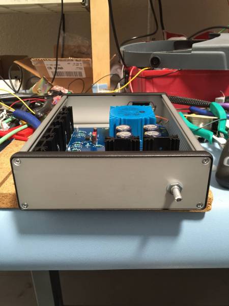
Being tested. The two 560 ohm resistors are the test load. (No, there is no headphone jack installed on this chassis, yet....)
Install whatever headphone jack you have/want on the chassis. Some people will want a big one, some a small, some will want the power switch on the front, others will want it on the back. Make a fantastically gorgeous chassis from wood, unicorn horn and platinum, or just use the cheap&cheerful Hammond that the PCB happens to fit. 🙂 It's DIY!
The name is still up in the air, things that have been discussed are "Perl D" (a workup of "PERsonal Listening Device" and Wayne's Grandmother named Pearl, of whom his previous DIY projects are named. )
I've come up with "Whammy". (Wayne's Headphone Amp Must Make Yourself) But that's kinda silly. (Although I do like it... 🙂 )
Any good name suggestions will be considered.
Well illustrated build guide here - "WHAMMY" Pass DIY headphone amp guide
Just to create some interesting discussion, here is a preview of the new PassDIY headphone amp. Wayne's been working on this, and everything so far has been very, very promising.
A few answers first --
As of this post in March '15, it's not yet available. Hopefully it will be for sale in the diyAudio store before summer.
These photos are of the first, non-conforming PCB. The final version will look very similar, the changes for the revision are all very minor, mostly silkscreen stuff.
Of course, it's Class-A. The output stage is really neat.
It has no 'Klunk.' 😛😛😛
It will be able to drive any headphone to deafening levels. Gain can also be turned down for super-sensitive headphones.
The whole circuit is on the one PCB. Input jacks, output jacks, and AC are all chassis mount. Of course, you could chassis mount the pot as well. Or use a fancy stepped attenuator. This is DIY, after all. 😀
A photo of a partially-stuffed PCB and some other parts.
The mosfets will mount to their own heatsinks on the edge. This will make it easy to utilize whatever chassis you like. In fact, the floor of a metal chassis will be enough heatsink and you could just mount the devices to that.
This is a nice touch - the PSU is able to be configured for fixed OR variable regulators. This is the basic hook-up for the 7815/7915 pair. But if you would like to use another 3-legged critter with the same pinout, feel free, the pads are there for the extra resistors and cap if needed.
(Obviously, this is a partially-stuffed PCB) The heart of the output circuit, the 4N35 optocoupler being used as the bias control. (This is a Nelson invention, I believe...) Bias is rock steady, and easily adjustable by simply changing the source resistors.
Oh, did I mention that you don't need matched output mosfet? 🙂 And that you can use Toshiba, Fairchild, IRF, or whatever you happen to have that's similar? Cool.
Being tested. The two 560 ohm resistors are the test load. (No, there is no headphone jack installed on this chassis, yet....)
Install whatever headphone jack you have/want on the chassis. Some people will want a big one, some a small, some will want the power switch on the front, others will want it on the back. Make a fantastically gorgeous chassis from wood, unicorn horn and platinum, or just use the cheap&cheerful Hammond that the PCB happens to fit. 🙂 It's DIY!
The name is still up in the air, things that have been discussed are "Perl D" (a workup of "PERsonal Listening Device" and Wayne's Grandmother named Pearl, of whom his previous DIY projects are named. )
I've come up with "Whammy". (Wayne's Headphone Amp Must Make Yourself) But that's kinda silly. (Although I do like it... 🙂 )
Any good name suggestions will be considered.
Last edited:
Thank you for posting all this!
I've been curious about the Pass DIY headphone amplifier.
What is the the purpose of the DIP-8 op-amp? Is it the first gain stage after the volume pot?
I've been curious about the Pass DIY headphone amplifier.
What is the the purpose of the DIP-8 op-amp? Is it the first gain stage after the volume pot?
+/-15V and 2SK2013/2SJ313 output per channel. That gives a good idea of maximum power.
I wonder if Nelson would let us pimp into the actual Pass Labs headphone amp ....
This is the real thing.
CES 2015: Pass Labs Upcoming Headphone Amplifier | InnerFidelity
Patrick
I wonder if Nelson would let us pimp into the actual Pass Labs headphone amp ....
This is the real thing.
CES 2015: Pass Labs Upcoming Headphone Amplifier | InnerFidelity
Patrick
just to stir things up , I have few questions :
-can we use 12V6 Accus ?
-will it drive F4 ?
-is it better than BA3 FE ?
-will it drive F4 ?
-can I use 32R phones ?
-can I use Stax statics ?
-will it drive F4?
no doubt , I'll be back with more ......

-can we use 12V6 Accus ?
-will it drive F4 ?
-is it better than BA3 FE ?
-will it drive F4 ?
-can I use 32R phones ?
-can I use Stax statics ?
-will it drive F4?
no doubt , I'll be back with more ......
slurpp yummy 🙂
Hmm.. wonder whats that op-amp socket doing in there ? 😀
Like the name you suggested Jim ....
Hmm.. wonder whats that op-amp socket doing in there ? 😀
Like the name you suggested Jim ....
Last edited:
-can we use 12V6 Accus ?
-will it drive F4 ?
-is it better than BA3 FE ?
-will it drive F4 ?
-can I use 32R phones ?
-can I use Stax statics ?
-will it drive F4?
In order:
12V6 Accus?? Not sure what that is...
Of course. 🙂 Heck - the suggested gain opamp is the OPA 2604, which can run on +/-24V. Get a slightly bigger transformer, use 7824/7924 regulators or 317/337, and swing even more volts.
No idea yet, I'm waiting for a couple of parts. The BA-3 gainstage is beautiful, as you know, but this will drive headphones, as the output stage is source-follower.
Yes.
Of course. Or 600ohm headphones. Or low-efficiency planar headphones. Or super-efficient IEM.
If you have the Stax step-up transformer, of course.
Yes. 😀
Hmm.. wonder whats that op-amp socket doing in there ?
The socket is to try different opamps. I've got a few on the bench I want to try.
Last edited:
Accu - shortie for Accumulator
ya know these things you're having in APC under your PC table and bed and even in airborne gadgets ......
just another thing - if reason for using OP as gain device is making Volksamp , why not using plain dirt IRFs on output , as main choice ?
I believe - majority of Greedy Boyz will rather choose slightly bigger PSU and heatsinks than fleabay hassle for Toshibas .......
only if you boyz intend to sell them through Store , as part of package
Last edited:
As you know, due to massive piles of the things in the secret Pass Labs vault and warehouse, Nelson and Wayne can only think in Toshiba. 🙂
This is not an issue, as the output stage works beautifully with Fairchild and IRF.
Because I have a bunch in my coffee can, the first prototype I build will use Fairchild FQP3N30/FQP3P20, Mouser has thousands in stock, for less than $1 each.
This is not an issue, as the output stage works beautifully with Fairchild and IRF.
Because I have a bunch in my coffee can, the first prototype I build will use Fairchild FQP3N30/FQP3P20, Mouser has thousands in stock, for less than $1 each.
Back to my original question from post 3...is the 2604 op-amp a gain stage or a servo as Zen suggested??
Edit--I see where 6L6 stated that it is for gain in post 10.
Edit--I see where 6L6 stated that it is for gain in post 10.
Last edited:
6L6, do you have part numbers for the Hammond enclosure you're using and the power transformer?
Does this use coupling caps on the outputs like the BA-3?
Thanks...
Does this use coupling caps on the outputs like the BA-3?
Thanks...
The case is Hammond 1455T2201 -- There are many different colors and options available in that same dimension. Metal or Plastic end panels, silver, blue, red, black, etc...
The transformer is the Amveco 70063K or Talema 70063K -- but it's a flexible design and you are not stuck with those specific part numbers. (Although it will need to have the same dimension and pinout if you want to PCB mount it.)
No caps on the output. It's DC coupled, something that the precision of the opamp is primarily responsible for. 🙂
Don't worry too much about parts and part numbers and such as yet... This is the prototype, and the version when released will have both a full article (in PassDIY style) and build guide (in diyAudio style). Also an annotated BOM which plenty of choices and substitutions for parts depending on your supplier.
I'm sure that many details are different, but it has some resemblance with the M3 from AMB.org .
Opamp input with mosfet output stage. I like the all in one pcb design!
I't would have been great to have a better power supply regulator, such as the super reg from the shop in the pcb, but that would increase the PCB area and complexity I know.
And why not a discrete input stage? The lsk trannies will be sold as matched pairs so the "where can I buy matched devices" problem is solved.
Ok, but designing a discrete amplifier from the ground up is different from throwing a discrete opamp in a design.
- Home
- Amplifiers
- Pass Labs
- New PassDIY Headphone Amp (now available)